Full Text Searchable PDF User Manual
I
NSTALLATION
G
UIDE
Delta Network Thermostat: BACstat II
DNT-T103 (Rev 4.1)
Document Edition 1.9
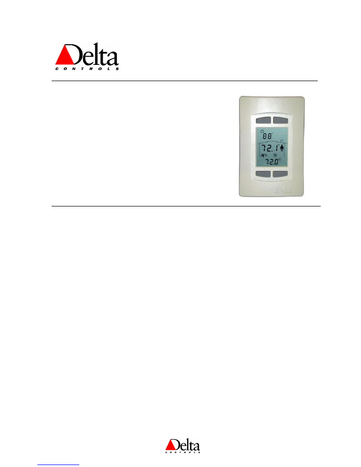
Product Description
The DNT-T103 is an intelligent room thermostat with a custom 3-
value, 96 segment LCD display. The DNT-T103 can communicate on
a BACnet MS/TP network or on Delta’s proprietary LINKnet network.
The DNT-T103 can display a wide-range of digital or analog values,
including setpoints, temperature, air flow, heating and cooling status,
fan speed, valve and damper position, and more.
When connected on a BACnet MS/TP network the DNT-T103
functions as an independent BACnet thermostat. When connected to a
controller, on a LINKnet network, it provides a programmable remote
sensor and expanded I/O capabilities. This version’s firmware can be
flash loaded over the network, and has a termination resistor that is
jumper selectable.
Contents
MODEL NUMBERS............................................................................................................. 2
PACKAGE CONTENTS ...................................................................................................... 2
OTHER RELEVANT DOCUMENTS................................................................................. 2
PRODUCT SPECIFICATIONS .......................................................................................... 2
PCB BOARD LAYOUT........................................................................................................ 4
JUMPERS .............................................................................................................................. 5
MOUNTING .......................................................................................................................... 6
WIRING DIAGRAM ............................................................................................................ 6
POWER.................................................................................................................................. 7
NETWORK CABLING & REQUIREMENTS .................................................................. 7
NETWORK TOPOLOGY.................................................................................................... 9
CAUTIONS & WARNINGS ................................................................................................ 9
COMPLIANCE DECLARATIONS .................................................................................. 10
Document Edition 1.9
Page 1 of 12
Error! No text of specified style in document.
DNT-T103 (Rev 4.1) Installation Guide
Model Numbers
Features
DNT-T103
DNT-H103B
DNT-T103-UL864
Internal Thermistor Input
Internal Humitity Input
Additional I/O (1 IP and 3 OP)
Backlighting Option
B
External Input Terminator
Option
X
Button Icons
INT
INT
INT
An appended button icon code must be included to specify the desired icons embossed on the buttons as
follows:
[
default
] Bottom 2 buttons are
▼
and
▲
(Setpoint Adjust), top 2 are
OFF
and
ON
INT
Bottom 2 buttons are
▼
and
▲
(Setpoint Adjust), top 2 are
O
and
I
–
International
You need not specify button icons if you want the default, but must specify INT if you want the international
button icons (i.e., DNT-T103-INT).
Package Contents
•
Delta Network Thermostat: BACstat II Product,
DNT-T103 (Rev 4.1)
•
DNT-T103 (Rev 4.1)
Installation Guide
Other Relevant Documents
•
Delta Controls Wiring and Installation Guidelines
•
BACstat II Application Guide (for Configuration & Programming)
•
ORCAview Operator Guide
•
ORCAview Technical Reference Manual
•
BACstat II, DAC and DCU Release Notes
Product Specifications
Power Requirements
•
24VAC, 50/60 Hz (Class 2)
•
41 VA maximum (with internally powered triacs at full load)
(3 VA with triacs externally powered)
Ambient Ratings
•
0°C to 40°C (32°F to 104°F)
•
10 to 90% RH (non-condensing)
Page 2 of 12
Document Edition 1.9

Delta Controls
Communication Port
LINKnet Connection
•
Communications Speed @ 76,800 bps
•
Up to 12 Devices per segment (depending on the controller), only two of which can be DNT or
DFM devices
BACnet MS/TP Connection
•
Communications Speed @ 9,600 or 19,200 or 38,400 or 76,800 bps (the default)
•
Maximum of 99 nodes per MS/TP segment (50 without a repeater)
•
Firmware can be flash loaded over the network
Temperature Sensor (IP1)
•
Thermistor Input – 10,000 ohm @ 77 ºF (25 ºC)
•
Accuracy of +/- 0.36 ºF from 32 - 158 ºF (+/- 0.2 ºC from 0 - 70 ºC)
•
Display Resolution of 0.1 ºF or ºC
•
Stability of 0.24 ºF over 5 years (0.13 ºC)
•
Optional Termination point for an External Thermistor on Input 1
•
Jumper Selectable for Internal or External Thermistor
•
Use a standard 10 K
Ω
Thermistor (10,000 ohm @ 77 ºF / 25 ºC)
Humidity Sensor (DNT-H103B Model Only)
•
Accuracy of +/-2% RH from 0-100% RH (25ºC, V
SUPPLY
= 2.6Vdc)
•
Display Resolution of 0.1 %
•
Stability of +/- 1% RH typical @ 50% RH over 5 years
*
Note:Extended exposure to >90% RH causes a reversible shift of 3% RH
Input (Additional)
•
1 Universal Input (10 bit), jumper configurable for the following input types:
0-5 VDC
0-10 VDC
10 K
Ω
Thermistor
Dry Contact (using 10 K
Ω
Thermistor jumper setting)
Outputs
•
3 Binary Triac Outputs
Switching 24 VAC @ 0.5 Amp maximum per output
Leakage Current per Triac is 100
µ
A
Jumper Selection for Internal or External Power
Software Configurable for Binary, PWM, Time Proportioned, or Tri-State Actuators
Technology
•
32-bit Processor c/w internal A/D, Flash, and RAM
•
3-value LCD c/w icons (96 total segments) and optional backlighting
•
4 stylized momentary push buttons with tactile feedback
Device Addressing
LINKnet Connection
•
Set via Keypad Configuration Setup
•
Address Range: 1 to 12
Document Edition 1.9
Page 3 of 12

Error! No text of specified style in document.
DNT-T103 (Rev 4.1) Installation Guide
BACnet MS/TP Connection
•
Set via Keypad Configuration Setup, or Software Setup
•
Keypad MAC Address Range: 1 to 99 per network segment
•
Software Address Range: As per the BACnet standard
•
Supports DNA – Delta’s intuitive addressing scheme
Size
•
5” x 3.25”x 1” (12.7 cm x 8.3 cm x 2.5 cm)
Weight
•
0.3 lb. (134 g)
PCB Board Layout
Page 4 of 12
Document Edition 1.9
Delta Controls
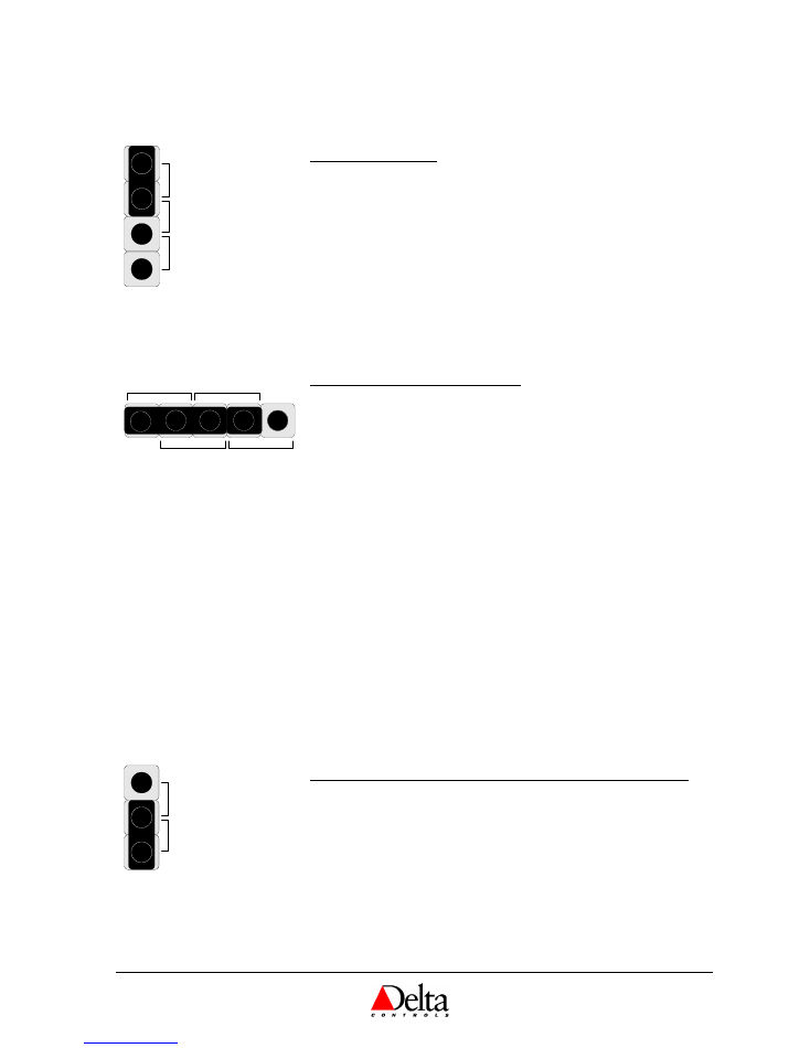
Jumpers
10K
5V
10V
INPUT SIGNAL TYPE
The input type is selected by placing the jumper in the correct location on
the Input Type Selector Block. The diagram to the left shows the factory
default selection of 10 K
Ω
.
10K
For 10 K
Ω
Thermistor temperature sensors, as well as Binary
or Dry Contact inputs.
5V
For sensors and other field devices that use a 5 VDC signal.
10V
For sensors and other field devices that use a 10 VDC signal.
INTERNAL
EXTERNAL
BINARY OUTPUT POWER SOURCE
The binary triac outputs can be selected to use either an internal or
external power source by placing the two jumpers in the correct locations.
The diagram to the left shows the factory default selection of Internal
Power Source.
Internal 24 VAC Power is provided internally from within the board
right to the output terminals. No external transformer is
required. The associated triac outputs are “hot” contacts. Note
that the power supply should be sized appropriately to handle
the additional loading.
External Power needs to be provided externally to the board from a
nearby transformer appropriately connected to the output wiring.
The associated triac outputs are
not
“hot” contacts, except by
means of the external transformer.
NOTE: Triacs are solid-state components that are only appropriate for
switching 24 VAC. They cannot be used to switch DC voltage. They also
have a small leakage current and may not be appropriate for certain “dry
contact” applications.
INTERNAL
EXTERNAL
INPUT CONNECTION SELECTOR – DNT-T103X MODELS ONLY
This jumper is used to select whether the internal Thermistor sensor or a
remotely located Thermistor is connected to IP1. The diagram to the left
shows the factory default selection of the Internal 10 K
Ω
Thermistor.
External For connecting a remotely located 10 K
Ω
Thermistor
temperature sensor to IP1, which is wired to the connection
terminals provided.
Internal For connecting the internal 10 K
Ω
Thermistor temperature
sensor to IP1.
Document Edition 1.9
Page 5 of 12
Error! No text of specified style in document.
DNT-T103 (Rev 4.1) Installation Guide
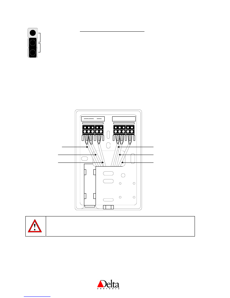
TERM
NO TERM
NETWORK TERMINATION RESISTOR
This jumper is used to select the termination resistor at each end of each
MS/TP network segment. The diagram to the left shows the factory
default selection of No Term.
Mounting
The BACstat II backplate is designed for mounting directly on standard North American, European or
Australian electrical boxes.
Wiring Diagram
Warning:
The network shield and any other bare wires should be bent back and taped to ensure that they
do not come into contact with the board electronics and cause a short. Otherwise you run the
risk of damaging the BACstat.
24~ GND IP2
+
-
PWR
NET
INPUT
OP1
COM
1&2 OP2
COM
3
OP3
24 VAC Power
Connection
Input 2
Connection
BACKPLATE
Output 1
Connection
Output 2
Connection
Output 3
Connection
Network
Connection
Page 6 of 12
Document Edition 1.9

Delta Controls
Notes:
1. Ensure you use the recommended balanced cable for the network and follow and follow the documented
procedures within
Delta Controls Wiring and Installation Guidelines
for MS/TP or LINKnet networks.
2. Do
not
use 4-wire multi-conductor cable for network and power, as it will not meet the balanced cable
requirements for the MS/TP or LINKnet networks. Use two separate cables: one for the network and the
other for power.
3. Do not terminate the network shield on the BACstats, but ensure shield conductivity is maintained along the
network from end-to-end with wire nuts as necessary.
4. If the same power source is used for more than one device, ensure that the transformer is properly sized for the
rated VA and that the same polarity is observed from device to device.
Power
The DNT-T103 requires a 24V AC Class 2 power supply. The VA requirements vary depending on the
output configuration as follows:
41 VA maximum (with internally powered triacs at full load)
3 VA (with triacs externally powered)
More than one device – not including DCUs or V2 products – may be connected to the same transformer, if
the transformer is properly sized (including line losses), and the polarity is observed between controllers (in
regards to 24~ and GND). The transformer must
ONLY
be used to provide power to other MS/TP
or
LINKnet devices and field devices powered through its outputs. Auxiliary field devices (i.e., 4-20 mA
devices) that don’t use ½ wave rectification must be powered separately.
For more information refer to the
Delta Controls Wiring and Installation Guidelines
.
Network & Cabling Requirements
Adhere to the following network and cabling requirements to ensure network stability and reliable communications,
particularly at high speeds on the RS-485 MS/TP or LINKnet networks.
Item
Description
Cabling
For MS/TP and LINKnet networks it is recommended that you use network cabling that
matches the following specifications:
•
Balanced 100 to 120
Ω
nominal impedance Twisted Shielded Pair (TSP) Cable
•
Nominal capacitance of 16 PF/FT or lower
•
Nominal velocity of propagation of 66% or higher
Topology
For MS/TP and LINKnet networks, ensure the cable is installed as a
daisy-chain
from one
device to the next.
Max. Nodes
•
MS/TP: The maximum number of devices per MS/TP network without any repeaters is
50
.
•
LINKnet: Up to a maximum of 12 Devices (depending on the controller), only two of
which can be DNT or DFM devices. (Refer to the Appendix called
Working with MS/TP
and LINKnet
in the
Technical Reference Manual
for more information.)
Termination
•
MS/TP: A termination resistor must be jumper selected at each end of each MS/TP network
Document Edition 1.9
Page 7 of 12

Error! No text of specified style in document.
DNT-T103 (Rev 4.1) Installation Guide
Boards
segment. Ensure you do not overlook this in laying out your network architecture.
•
LINKnet: Jumper select a termination resistor on each end of the network when there
are more than 2 nodes. Termination resistors do not need to be installed for one or two
nodes.
Repeater
•
MS/TP: A repeater (RPT-768) is not necessary unless more than 50 nodes will be installed
on a network
or
you need to extend the network beyond 4000 ft (1220 m).
•
LINKnet: Repeaters should not be necessary. Ensure the maximum distance is no
more than 1000 ft (300 m).
For more information refer to the
Delta Controls Wiring and Installation Guidelines
.
Page 8 of 12
Document Edition 1.9
Delta Controls
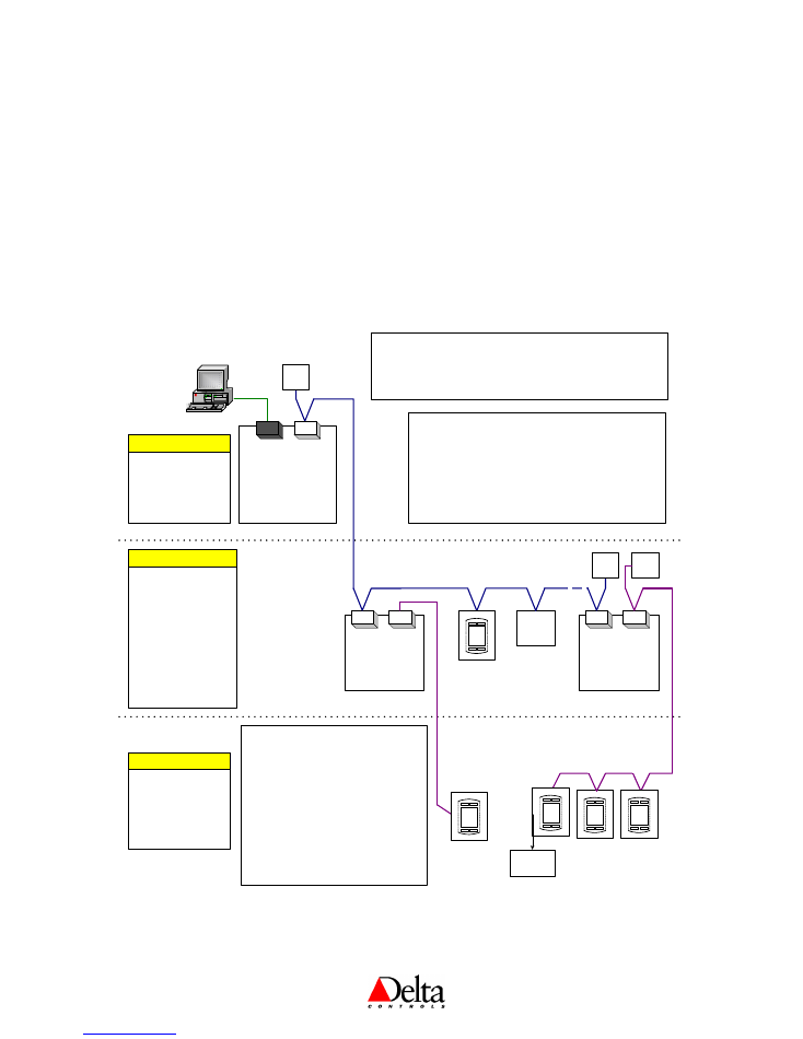
Network Topology
1. BACstats Configured as MS/TP Subnet Devices
With V3.21 firmware or higher, one possible MS/TP network architecture has the MS/TP devices configured as
Subnet devices, which allows BACstats to reside on the MS/TP network with other Subnet devices. Note that
V3.21 requires a DCU, while V3.22 or higher may use any System Controller instead.
2. BACstats Configured as LINKnet Devices
The BACstat may reside on LINKnet instead of MS/TP. However, this requires a controller that supports a
LINKnet network for I/O expansion. The maximum LINKnet devices with or without I/O depends on the
controller. All built-in applications must be disabled, but the I/O may be muxed (with V3.22 firmware).
DCU/DSC
(System Device)
BACnet (MS/TP) - Level 3 Network (Subnet)
DAC
(Subnet
Device)
TRM
DAC
(Subnet
Device)
TRM
Level 4
Network
(LINKnet)
16x16 Controller
12x12 Controller
12x8 Controller
6x6 Controller
Room Controller
VAV/VVT Controller
Lighting Controller
BACstat I
BACstat II
(with or without I/O)
Input Field Modules
Subnet Devices
DSC-1616EX [DCU]
DSC-1616(H/E)
DSC-1212(H/E)
DSC-1280(H/E)
DSC-T305
System Devices
RS-485
NET1
NET2
NET1
NET2
RS-232
BACstat I
BACstat II
(with No I/O)
BACstat II
(with muxed I/O)
I/O Field Modules
LINKnet Devices
TRM
Level 4
Network
(LINKnet)
LINKnet Notes:
1. Ensure you use the recommended
balanced cable.
2. Ensure the cable is installed as a daisy-
chain from one device to the next. (1000'
or 300m maximum).
3. *Ensure you jumper select a MS/TP
termination resistor when you have more
than 1 or 2 devices.
4. Depending on the controller, up to 12
devices are supported on a LINKnet
network, with limitations on how many of
these may have I/O. (Refer to the
Technical Reference Manual.)
ORCAview
OWS
DFM
Ethernet Note:
If the DCU or DSC has Ethernet capability, it may exist on an
Ethernet network with other controllers in the same building, on which
the ORCAview OWS could reside as well (instead of PTP).
PTP
MS/TP Notes:
1. Ensure you use the recommended balanced cable.
2. Ensure the cable is installed as a daisy-chain from one
device to the next (4,000' or 1220m maximum).
3. *Ensure you jumper select a termination resistor on each
end of each MS/TP network.
4. The maximum nodes per MS/TP network is 50 without a
repeater or up to 99 with at least one repeater (RPT-768).
Network Diagram
(with V3.22 Firmware)
* Note 3
Document Edition 1.9
Page 9 of 12

Error! No text of specified style in document.
DNT-T103 (Rev 4.1) Installation Guide
Cautions and Warnings
The DNT-T103 BACstat II is an electrostatically sensitive device. An ESD protection (ground
strap) should be unnecessary if sufficient care is taken in handling because the electronics are
contained within the product housing.
UL 864 Specific Considerations
•
Use the transformer by Core Components Inc., Model No. 120-024-100-2TF-CB to power the device.
•
Use only UL Listed Class 2 Power Supplies for auxiliary field devices.
Page 10 of 12
Document Edition 1.9
Delta Controls
Compliance Declarations
FCC Compliance Information
This equipment has been tested and found to comply with the limits for a Class B digital device, pursuant to
Part 15 of the FCC Rules. These limits are designed to provide reasonable protection against harmful
interference in a residential installation. This equipment generates, uses, and can radiate radio frequency
energy and, if not installed and used in accordance with the instructions, may cause harmful interference to
radio communications. However, there is no guarantee that interference will not occur in a particular
installation. If this equipment does cause harmful interference to radio or television reception, which can be
determined by turning the equipment off and on, the user is encouraged to try to correct the interference by one
or more of the following measures:
•
Reorient or relocate the receiving antenna.
•
Increase the separation between the equipment and receiver.
•
Connect the equipment into an outlet on a circuit different from that to which the receiver is
connected.
•
Consult the dealer or an experienced radio/TV technician for help.
Industry Canada Compliance Statement
ICES-003 This Class B digital apparatus meets all requirements of the Canadian Interference-Causing
Equipment Regulations.
Cet appareil numérique de la Classe B Respecte toutes les exigences du Règlement sur le matérial
brouiller du Canada.
UL Compliance Information
This product conforms to the following UL requirements:
•
UL916: Energy Management Equipment
•
UL 864: Control Units and Accessories for Fire Alarm Systems
•
CAUTION – Risk of Electric Shock – More than one disconnect switch may
be required to de-energize the equipment before servicing
•
All terminals are acceptable for Class 2 circuit connection only
•
CAUTION – Input Class 2 Power Supplies are interconnected. To Reduce
the Risk of Fire or Electric Shock, Use only Class 2 sources Suitable for
Interconnection
•
Use Copper Conductor Only
•
Select an external power supply that is certified for safety for the correct
destination country and that has an output rating, which is considered an NEC
Class 2 or Limited Power Source with the rating not to exceed 30 V rms, 42.4
V peak, 100 VA.
•
Apply minimum 6.0 lb-in torque for tightening field wires into the terminal
blocks.
Document Edition 1.9
Page 11 of 12

Error! No text of specified style in document.
DNT-T103 (Rev 4.1) Installation Guide
Page 12 of 12
Document Edition 1.9
CE - DECLARATION OF CONFORMITY
according to ISO/IEC Guide 22 and EN 45014
Manufacturer's Name:
Delta Controls
Manufacturer's Address:
17850 56
th
Avenue
Surrey, British Columbia
Canada
V3S
1C7
declares that the product (s):
Product Name:
BACstat II - Binary
Model Numbers:
DNT-T103
Product Options:
All
conforms to the following Product Specifications:
EMC:
EN 55022:1994
Radiated and Conducted Emissions
Class B
EN 50082-1:1997
Generic Immunity Standard
EN 61000-4-2:1995 + A1:1999 ESD Immunity
Level A
EN 61000-4-3:1996
RF Electromagnetic Field Immunity
Level A
ENV 50204:1995
RF Electromagnetic Field Immunity (Keyed)
Level A
EN 61000-4-4:1995
EFT/Burst Immunity
Level B
EN 61000-4-5:1995
Surge Immunity
Level B
EN 61000-4-6:1996
Conducted RF Disturbances Immunity
Level A
EN 61000-4-11:1994
Voltage Dips / Interruptions
Level B/C
Supplementary Information:
The product(s) herewith comply with the requirements of the EMC Directive
89/336/EEC. The product(s) were tested in a typical configuration.
Lee
Dickson
Quality Assurance Manager