Full Text Searchable PDF User Manual
INSTALLATION MANUAL
ZONE CONTROLLER
Air Conditioners
MODELS
BRC230Z4
BRC230Z8
BRC24Z4
BRC24Z8
BRCSZC
PLEASE READ THESE INSTRUCTIONS CAREFULLY BEFORE INSTALLATION.
KEEP THIS MANUAL IN A HANDY PLACE FOR FUTURE REFERENCE.

2

3
CONTENTS
SAFETY CONSIDERATIONS . . . . . . . . . . . . . . . . . . . . . . . . . . . . . . . . . . . . . . . . . . . . . . . . . . . . . . . . 4
ACCESSORIES . . . . . . . . . . . . . . . . . . . . . . . . . . . . . . . . . . . . . . . . . . . . . . . . . . . . . . . . . . . . . . . . . . . 5
HOW TO INSTALL BRC230Z4 / BRC230Z8. . . . . . . . . . . . . . . . . . . . . . . . . . . . . . . . . . . . . . . . . . . . . 6
HOW TO INSTALL BRC24Z4 / BRC24Z8. . . . . . . . . . . . . . . . . . . . . . . . . . . . . . . . . . . . . . . . . . . . . . . 8
INSTALLING REMOTE SENSOR 1 & 2 . . . . . . . . . . . . . . . . . . . . . . . . . . . . . . . . . . . . . . . . . . . . . . . 10
FIELD SETTING. . . . . . . . . . . . . . . . . . . . . . . . . . . . . . . . . . . . . . . . . . . . . . . . . . . . . . . . . . . . . . . . . . 10
DSI SWITCH SETTINGS . . . . . . . . . . . . . . . . . . . . . . . . . . . . . . . . . . . . . . . . . . . . . . . . . . . . . . . . . . . 12
HOW TO CONNECT BRCW902A15 EXTENSION CABLE . . . . . . . . . . . . . . . . . . . . . . . . . . . . . . . . 12
FAULT / INSPECTION / TEST MODE. . . . . . . . . . . . . . . . . . . . . . . . . . . . . . . . . . . . . . . . . . . . . . . . . 12
FAULT CODE SHEET . . . . . . . . . . . . . . . . . . . . . . . . . . . . . . . . . . . . . . . . . . . . . . . . . . . . . . . . . . . . . 13
CONTROLLER MOUNTING BRACKET . . . . . . . . . . . . . . . . . . . . . . . . . . . . . . . . . . . . . . . . . . . . . . . 14
ELECTRIC WIRING WORK. . . . . . . . . . . . . . . . . . . . . . . . . . . . . . . . . . . . . . . . . . . . . . . . . . . . . . . . . 14
SUB CONTROLLER INSTRUCTIONS . . . . . . . . . . . . . . . . . . . . . . . . . . . . . . . . . . . . . . . . . . . . . . . . 15
4
SAFETY CONSIDERATIONS
Please read these “SAFETY CONSIDERATIONS” carefully before installing the zone controller and be sure to install it correctly.
After completing the installation, make sure that the zone controller operates properly. Please instruct the customer on how to
operate the zone controller.
Please inform the customer that they should store this installation manual along with the operation manual for future reference.
This controller comes under the term “appliances not accessible to the general public”.
Meaning of warning and caution symbols
WARNING
. . . . . . Failure to observe a warning may result in death, injury or damage to the equipment.
CAUTION
. . . . . . Failure to observe a caution may result in injury or damage to the equipment.
WARNING
Ask your Dealer or qualified personnel to carry out installation work. Do not try to install the zone controller yourself.
Perform installation work in accordance with this installation manual. Improper installation may result in electric shock or fire.
Be sure to use only the specified accessories and parts for installation work. Failure to use the specified parts may result in electric
shock, fire or the zone controller failing.
Make sure that all electrical work is carried out by qualified personnel according to local laws, regulations and this installation manual.
An insufficient power supply capacity or improper electrical construction may lead to electric shock or fire.
Make sure that all wiring is secured, the specified wires are used, and no external forces act on the terminal connections or wires.
Improper connections or installation may result in fire.
When wiring the power supply and connecting the wiring between the unit electrical box, zone controller box and zone motors,
position the wires so that the zone controller box cover can be securely fastened.
Improper positioning of the zone controller box cover may result in electric shock, fire or the terminals overheating.
Before obtaining access to the terminals and electrical parts, all supply circuits must be disconnected.
Do not install the remote controller where it may be exposed to rain or moisture. Water or other fluids on the electrical components
may result in fire or electric shock.
Earth the zone controller box. Do not connect the earth wire to gas or water pipes, a lightning conductor or a telephone ground wire.
Incomplete earthing may result in electric shock.
Be sure to install an earth leakage breaker. Failure to install an earth leakage breaker may result in electric shock.
Do not install the remote controller where flammable gases may leak, where there are carbon fibre or ignitable dust suspended in the air,
or where volatile flammables such as thinner or gasoline are handled.
Do not install the remote controller where the area is filled with steam or the ground is always wet. Insulation of the electric components
may be damaged in such conditions and may result in electric shock.
CAUTION
Install the zone controller, power cords and connecting wires at least 1 metre away from televisions or radios in order to
prevent image interference or noise.
(Depending on the radio waves, a distance of 1 metre may not be sufficient enough to eliminate noise.)
Do not install the zone controller in the following locations:
(a) Where a mineral oil mist, oil spray or vapour is produced, for example in a kitchen.
Plastic parts may deteriorate.
(b) Near machinery emitting electromagnetic waves.
Electromagnetic waves may disturb the operation of the control system and result in a malfunction of the equipment.
(d) Where salinity in the air is relatively high.
5
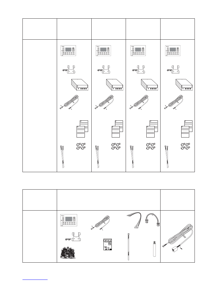
ACCESSORIES
MODEL
MODEL
(SUB CONTROLLER) BRCSZC
15M
EXTENSION
LEAD
BRCW902A15
SHAPE
&
QUANTITY
SHAPE
&
QUANTITY
(4 zone 230-240V)
BRC230Z4
(8 zone 230-240V)
BRC230Z8
(4 zone 24VAC)
BRC24Z4
(8 zone 24VAC)
BRC24Z8
CABLE
TIE
X 5
SUB ZONE
KEYPAD
X 1
P1/P2
HARNESS
X 1
POWER
HARNESS
X 1
PCB
POST
X 4
INTERFACE
PCB X 1
15M
CONTROLLER
CABLE
X 1
X 1
SCREW
X 2
MOUNTING
BRACKET
INSTALLATION
INSTRUCTION
X 1
230-240V
8 ZONE
CONTROL
BOX
X 1
M6 SCREW
X 4
SPARE
CABLE
TIE
X 2
ZONE
KEYPAD
X 1
15M
CONTROLLER
CABLE
X 1
24V
4 ZONE
CONTROL
BOX
X 1
M6 SCREW
X 4
SPARE
CABLE
TIE
X 2
ZONE
KEYPAD
X 1
15M
CONTROLLER
CABLE
X 1
SCREW
X 2
MOUNTING
BRACKET
X 1
INSTALLATION
INSTRUCTION X 1
OPERATION
MANUAL
X 1
INSTALLATION MANUAL
ZONE CONTROLLER
Air Conditioners
MODELS
BRC230Z4
BRC230Z8
BRC24Z4
BRC24Z8
BRCSZC
PLEASE READ THESE INSTRUCTIONS CAREFULLY BEFORE INSTALLATION.
KEEP THIS MANUAL IN A HANDY PLACE FOR FUTURE REFERENCE.
OPERATION MANUAL
ZONE CONTROLLER
Air Conditioners
MODELS
BRC230Z4
BRC230Z8
BRC24Z4
BRC24Z8
BRCSZC
PLEASE READ THESE INSTRUCTIONS CAREFULLY BEFORE INSTALLATION.
KEEP THIS MANUAL IN A HANDY PLACE FOR FUTURE REFERENCE.
24V
8 ZONE
CONTROL
BOX
X 1
M6 SCREW
X 4
SPARE
CABLE
TIE
X 2
ZONE
KEYPAD
X 1
15M
CONTROLLER
CABLE
X 1
SCREW
X 2
MOUNTING
BRACKET
X 1
INSTALLATION
INSTRUCTION X 1
OPERATION
MANUAL
X 1
INSTALLATION MANUAL
ZONE CONTROLLER
Air Conditioners
MODELS
BRC230Z4
BRC230Z8
BRC24Z4
BRC24Z8
BRCSZC
PLEASE READ THESE INSTRUCTIONS CAREFULLY BEFORE INSTALLATION.
KEEP THIS MANUAL IN A HANDY PLACE FOR FUTURE REFERENCE.
OPERATION MANUAL
ZONE CONTROLLER
Air Conditioners
MODELS
BRC230Z4
BRC230Z8
BRC24Z4
BRC24Z8
BRCSZC
PLEASE READ THESE INSTRUCTIONS CAREFULLY BEFORE INSTALLATION.
KEEP THIS MANUAL IN A HANDY PLACE FOR FUTURE REFERENCE.
230-240V
4 ZONE
CONTROL
BOX
X 1
M6 SCREW
X 4
SPARE
CABLE
TIE
X 2
ZONE
KEYPAD
X 1
15M
CONTROLLER
CABLE
X 1
SCREW
X 2
MOUNTING
BRACKET
X 1
INSTALLATION
INSTRUCTION X 1
OPERATION
MANUAL
X 1
INSTALLATION MANUAL
ZONE CONTROLLER
Air Conditioners
MODELS
BRC230Z4
BRC230Z8
BRC24Z4
BRC24Z8
BRCSZC
PLEASE READ THESE INSTRUCTIONS CAREFULLY BEFORE INSTALLATION.
KEEP THIS MANUAL IN A HANDY PLACE FOR FUTURE REFERENCE.
OPERATION MANUAL
ZONE CONTROLLER
Air Conditioners
MODELS
BRC230Z4
BRC230Z8
BRC24Z4
BRC24Z8
BRCSZC
PLEASE READ THESE INSTRUCTIONS CAREFULLY BEFORE INSTALLATION.
KEEP THIS MANUAL IN A HANDY PLACE FOR FUTURE REFERENCE.
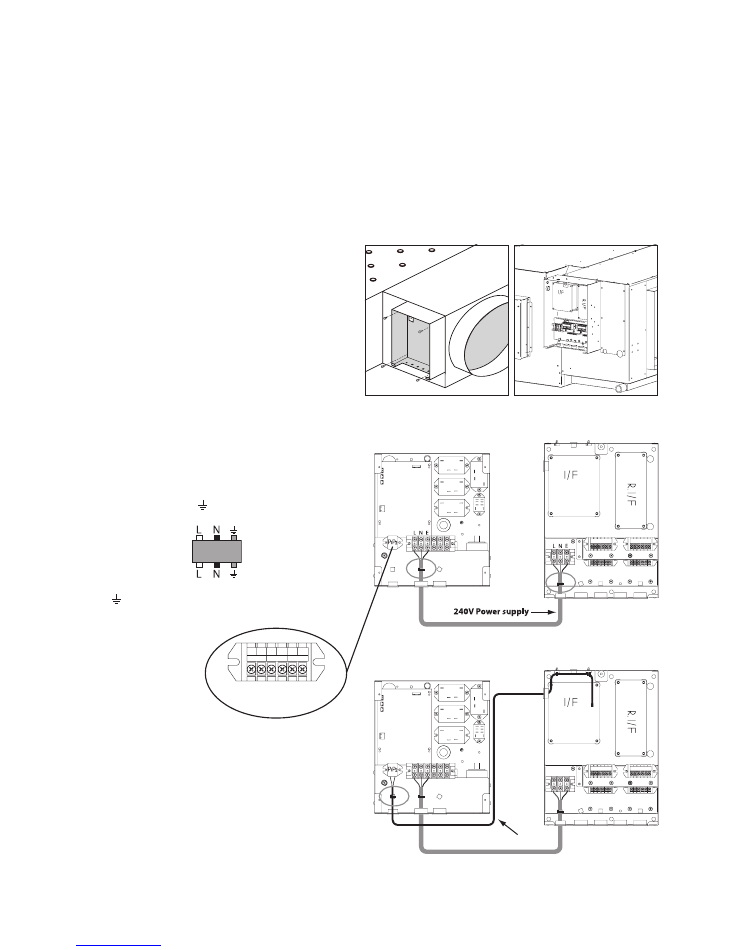
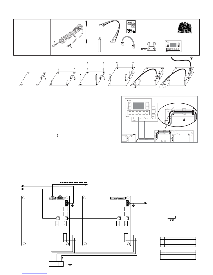
1. Insert one end of P1/P2 harness into socket S9 located on the lower interface
PCB (A1P). Diagram 1.
2. Loosen (4) plastic nuts. Diagram 2.
3. Screw in (4) PCB post and gently tighten. Diagram 3
4. Install upper Interface PCB (A2P) in the same direction as lower Interface
PCB (A1P). Diagram 4.
5. Add (4) plastic nuts and gently tighten. Diagram 4.
6. Plug the loose end of P1/P2 harness into socket S7 of upper Interface PCB
(A2P). Diagram 4.
7. Wire Power harness into LN terminal block X3M (Black- A)
(White –N) (Green – Earth). Diagram 5.
8. Plug the other end of the power harness into S1 socket of the upper Interface
PCB (A2P). Diagram 5.
9. Pass the Remote controller cable through the 2 open cable ties. If the cable
ties have already been tightened cut the cable ties and use the spare cable
ties supplied to secure the controller leads. Diagram 7.
10. Plug the remote controller cable connector into socket S8 of upper Interface
PCB (A2P). Diagram 6.
11. Wire the controller lead earth shield cable to the earth shield post. Diagram 7.
TO REMOTE CONTROLLER
TO RELAY PCB S19 (8 ZONE ONLY)
TO RELAY PCB S19 (4 ZONE)
A2P
A1P
L N E
S12
S7 S8
S2
S1
S1
S3
S13
S12
S13
S8
TN1
(NOTE 2)
TN2
S7 S8
S2
S3
S8
TO SUB CONTROLLER
TN1
TN2
TO P1 P2 TERMINAL
BLOCK (NOTE1)
B
W
G X3M
Sub Controller Instructions BRCSZC
S9
S9
S9
S9
S1
A N
S7
1
2
3
4
5
6
7
S9
S8
A N
ACCESSORIES
CABLE
TIE
X 5
SUB ZONE
KEYPAD
X 1
P1/P2
HARNESS
X 1
POWER
HARNESS
X 1
PCB
POST
X 4
INTERFACE
PCB X 1
15M
CONTROLLER
CABLE
X 1
MODE
FAN
TEMP
ADJUS
T
BUT
TO
N
TEMP
SHIF
T
7 DA
Y
TIME CLOC
K
ON/OFF
TIME
R
ENTE
R
CLEA
R
TEST/EXI
T DAY TIME ZONE1 ZONE2 ZONE3 ZONE
4
SEL
SENSO
R FIX SENSO
R
ZONE5 ZONE6 ZONE7 ZONE
8
MODE
FAN
TEMP
ADJUS
T
BUT
TON
TEMP
SHIF
T
7 DA
Y
TIME CLOC
K
ON/OFF
TIME
R
ENTE
R
CLEA
R
TEST/EXI
T DAY TIME ZONE1 ZONE2 ZONE3 ZONE
4
SEL
SENSO
R FIX SENSO
R ZONE5 ZONE6 ZONE7 ZONE
8
4PDA0687
NOTE:
1.
P1 P2 TERMINAL BLOCK
LOCATED IN THE ELECTRICAL
BOX OF INDOOR UNIT.
2.
TN1, TN2 ONLY USE DAIKIN
REMOTE TEMPERATURE
SENSOR KRCSO1-1
3. :TERMINAL
:CONNECTOR
4.
SYMBOLS SHOW AS FOLLOWS
B: BLACK
W: WHITE
G: GREEN
A1P INTERFACE PRINTED CIRCUIT BOARD
A2P INTERFACE PRINTED CIRCUIT BOARD
TN1 REMOTE SENSORS 1
TN2 REMOTE SENSORS 2
S1
S9-S7
S7
S8
CONNECTOR
230~240V
A1P 7 A2P COMMUNICATION
A1P INDOOR COMMUNICATION
REMOTE CONTROLLER
A1P
A2P
X3M
SCREW
X 2
MOUNTING
BRACKET
INSTALLATION
INSTRUCTIONS
INST
ALLA
TION
MANUAL
ZONE
CONTROLLER
Air
Conditioners
MODELS
BRC230Z4
BRC230Z8
BRC24Z4
BRC24Z8
BRCSZC
PLEASE
READ
THESE
INSTRUCTIONS
CAREFULL
YBEFORE
INST
ALLA
TION.
KEEP
THIS
MANUAL
IN A
HANDY
PLACE
FOR
FUTURE
REFERENCE.
OPTIONAL ACCESSORIES
6
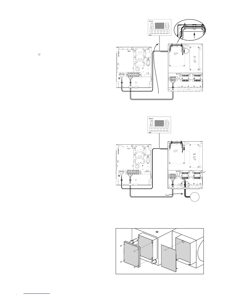
HOW TO WIRE & INSTALL BRC230Z4 / BRC230Z8
Step 1.
Attach the Zone control box to the body of the indoor
unit using the (4) M6 screws supplied. (Fig.1)
Be careful not to cause damage to the internal
components of the Zone control box when attaching the
box to the indoor unit.
Step 2.
Pass both ends of the field supplied cable through the
plastic bushes of the indoor unit electrical box and zone
controller box. Strip both ends of the cable. Connect the
stripped wires to the LN terminals of the unit electrical
box and the zone controller box.
By using a cable tie (field supplied), secure both ends of
the LN cable to the anchor as shown in (Fig.2)
ensuring the cable tie is secured to the outer insulation
of the cable.
Step 3.
Connect the loose end of P1 P2 communication cable to
the P1 P2 terminal block of the indoor unit electrical box.
(No polarity)
By using a cable tie (field supplied) secure P1 P2
communication cable to the anchor as shown in (Fig.3).
P1 P1 Communication wire
L N E
L N E
S7
Note 1:
You may find it easier to wire the control box before mounting the box to the indoor unit, for example when the
ceiling space is tight. If you choose to wire the control box before mounting it to the indoor unit ensure to allow
adequate cable length.
Note 2:
Please refer to Electric Wiring Work Pg. 14 of this manual to determine cable connection style and to ensure the
wiring connections are appropriate.
Note 3:
Ensure all field wiring passes through the black plastic wiring bushes located at the bottom of the controller box.
Fig.1
Fig.2
Fig.3
FDYQ(N)71-160
FDYQ(N)180-250
Indoor Unit Electrical Box Zone Controller Box
Indoor Unit Electrical Box Zone Controller Box
P1 P2 F1 F2 T1 T2
REMOTE
CNTRL
TRANSMISSION
WIRING
FORCED
OFF
Indicates 180 - 250
terminal block
7
Step 4.
Pass the remote controller cable through the two open
cable ties (factory supplied).
Connect the remote controller cable to the Interface PCB
( A1P) by inserting the remote controller cable plug into
socket S8. (Fig.4)
Wire the shield wire of the remote controller cable to
the shield fastening point. (Fig.4a)
Note 4:
When installing KRCSO1-1 (option) or BRCSZC (option),
do not tighten the cable ties until you have passed all
cables through the 2 open cable ties.
Tighten the 2 cable ties to anchor. (Fig.4a)
Step 5.
Wire the zone motors to the zone motor terminal blocks
X4M (Fig.5) (zone motor field supplied)
Pay close attention to the terminal labelling.
When wiring “motor open motor closed” zone motors
ensure open, close & neutral wires are wired to
respective terminals.
Note 5:
For zone motors that require earthing.
(Ensure zone motors are earthed to the individual earth
connections provided.)
Open = Active
Closed = Active
Common = Neutral
When using a spring return zone motor only use the
Open & Common terminal connections.
By using a cable tie (field supplied), secure the zone
motor leads to the anchor as shown in (Fig.5) ensuring
the cable tie is secured to the outer insulation of the
cable.
Note 6:
Refer to DSI settings on page 12 before installing the
zone controller box cover.
Step 6.
Install the indoor unit electrical box cover and the zone
control box cover. (Fig.6)
Ensure the cover fits tightly and cables are not in contact
with the underside of cover or cover edges.
Remote controller wiring
L N E
L N E
S7
MODE
FAN
TEMP
ADJUST
BUTTON
TEMP
SHIFT
7 DAY
TIME CLOCK
ON/OFF
TIMER
ENTER
CLEAR
TEST/EXIT
DAY TIME
ZONE1
ZONE2
ZONE3
ZONE4
SEL SENSOR
FIX SENSOR
ZONE5
ZONE6
ZONE7
ZONE8
(AIP)
S8
Zone motor connection
L N E
L N E
S7
MODE
FAN
TEMP
ADJUST
BUTTON
TEMP
SHIFT
7 DAY
TIME CLOCK
ON/OFF
TIMER
ENTER
CLEAR
TEST/EXIT
DAY TIME
ZONE1
ZONE2
ZONE3
ZONE4
SEL SENSOR
FIX SENSOR
ZONE5
ZONE6
ZONE7
ZONE8
ZONE
MOTOR
X4M
Fig.4
Fig.4a
Fig.5
Fig.6
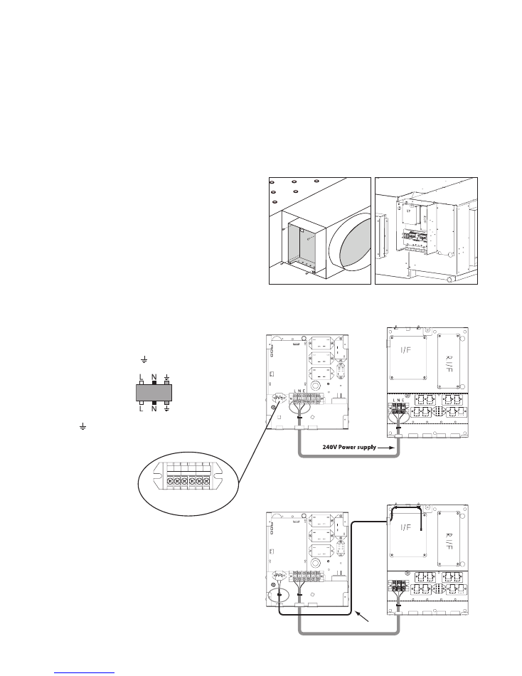
Step 1.
Attach the Zone control box to the body of the indoor
unit using the (4) M6 screws supplied. (Fig.1)
Be careful not to cause damage to the internal
components of the Zone control box when attaching the
box to the indoor unit.
Step 2.
Pass both ends of the field supplied cable through the
plastic bushes of the indoor unit electrical box and zone
controller box. Strip both ends of the cable. Connect the
stripped wires to the LN terminals of the unit electrical
box and the zone controller box.
By using a cable tie (field supplied), secure both ends of
the LN cable to the anchor as shown in (Fig.2)
ensuring the cable tie is secured to the outer insulation
of the cable.
Step 3.
Connect the loose end of P1 P2 communication cable to
the P1 P2 terminal block of the indoor unit electrical box.
(No polarity)
By using a cable tie (field supplied) secure P1 P2
communication cable to the anchor as shown in (Fig.3).
Note 1:
You may find it easier to wire the control box before mounting the box to the indoor unit, for example when the
ceiling space is tight. If you choose to wire the control box before mounting it to the indoor unit ensure to allow
adequate cable length.
Note 2:
Please refer to Electric Wiring Work Pg. 14 of this manual to determine cable connection style and to ensure the
wiring connections are appropriate.
Note 3:
Ensure all field wiring passes through the black plastic wiring bushes located at the bottom of the controller box.
8
24VAC
24VAC
P1 P1 Communication wire
L N E
L N E
S7
HOW TO WIRE & INSTALL BRC24Z4 / BRC24Z8
Fig.2
Fig.3
Indoor Unit Electrical Box Zone Controller Box
Fig.1
FDYQ(N)71-160
FDYQ(N)180-250
Indoor Unit Electrical Box Zone Controller Box
P1 P2 F1 F2 T1 T2
REMOTE
CNTRL
TRANSMISSION
WIRING
FORCED
OFF
Indicates 180 - 250
terminal block
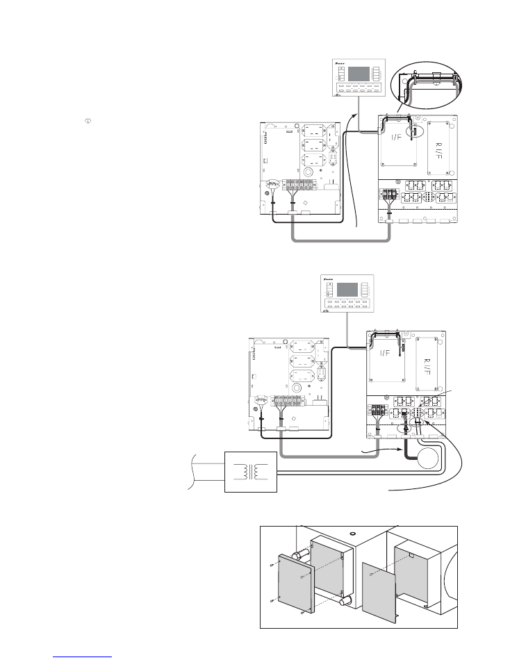
9
Step 4.
Pass the remote controller cable through the two open
cable ties (factory supplied).
Connect the remote controller cable to the Interface
PCB ( A1P) by inserting the remote controller cable plug
into socket S8. (Fig.4)
Wire the shield wire of the remote controller cable to
the shield fastening point. (Fig.4a)
Note 4:
When installing KRCSO1-1 (option) or BRCSZC
(option), do not tighten the cable ties until you have
passed all cables through the 2 open cable ties.
Tighten the 2 cable ties to anchor. (Fig.4a)
Step 5.
Connect the zone motor RJ12 plugs into the respective
zone sockets. (zone motors and leads field supplied)
By using a cable tie secure zone motor leads to the
anchor as shown in (Fig.5)
Step 6.
Wire 24V AC supply leads from the transformer (field
supplied) to the terminal block X5M located in the
zone controller box. (Fig.5)
By using a cable tie secure the 24V supply cable to
the anchor. (Fig.5)
Important: Ensure the transformer is adequately
sized for the zone motor electrical load and is
suitable for the installation conditions. (FIELD
SUPPLIED)
Note5:
Refer to DSI settings on page12 before installing the
zone controller box cover.
Step 7.
Install the indoor unit electrical box cover and the Zone
control box cover. (Fig.6)
Ensure the cover fits tightly and cables are not in
contact with the underside of cover or cover edges.
24VAC
Remote controller wiring
L N E
L N E
S7
(AIP)
S8
MODE
FAN
TEMP
ADJUST
BUTTON
TEMP
SHIFT
7 DAY
TIME CLOCK
ON/OFF
TIMER
ENTER
CLEAR
TEST/EXIT
DAY TIME
ZONE1
ZONE2
ZONE3
ZONE4
SEL SENSOR
FIX SENSOR
ZONE5
ZONE6
ZONE7
ZONE8
Fig.4
Fig.6
24VAC
Zone motor connection
L N E
L N E
S7
X5M
TRANSFORMER
CONNECTION
MODE
FAN
TEMP
ADJUST
BUTTON
TEMP
SHIFT
7 DAY
TIME CLOCK
ON/OFF
TIMER
ENTER
CLEAR
TEST/EXIT
DAY TIME
ZONE1
ZONE2
ZONE3
ZONE4
SEL SENSOR
FIX SENSOR
ZONE5
ZONE6
ZONE7
ZONE8
ZONE
MOTOR
220-240 V
24VAC
24 VAC
P
R
I
M
A
R
Y
S
E
C
O
N
D
A
R
Y
Fig.5
Fig.4a
INSTALLING REMOTE SENSOR 1 & 2
10
0
10
0
1
0
10
0
1
0
23
6
1
0
23
6
2
0 2
0 2
23
6
23
6
Step 1
Step 2
Step 3
Step 4
Step 5
Step 6
Blinking
Blinking
Blinking
Blinking
Blinking
Blinking
Blinking
Blinking
Blinking
Blinking
KRCSO1-1
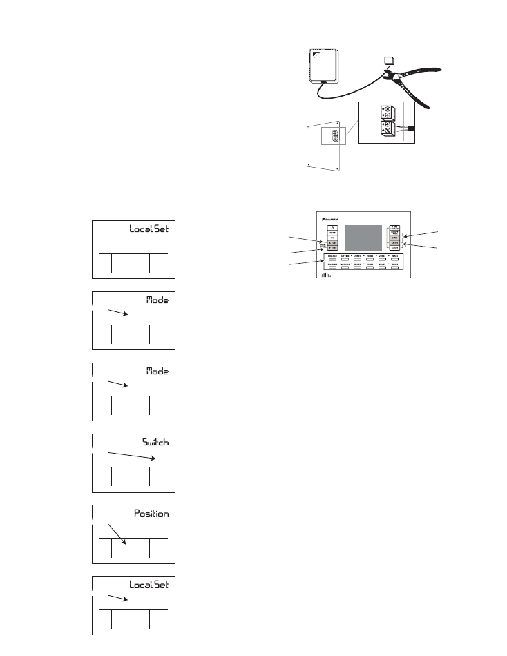
Step 1.
Using Daikin option KRCSO1-1 cut plug off lead. (Fig.7)
Step 2.
Carefully strip the insulation of the leads exposing the core wire. Insert
the 2 stripped wires into the two terminal holes of terminal block TN1.
Repeat the process using terminal block TN2 if a second sensor is
required.
Step 3.
Carefully tighten the terminal screws, be careful not to over tighten the
screws. (When connecting 1 sensor use terminal block TN1) Please
refer to note 4. (Page 7 or 9) Ensure cables are secured by the 2 cable
ties provided.
Do not allow KRCSO1-1 cables to come in contact
with live power or PCB’s.
FIELD SETTINGS
TEMP UP
TEMP DOWN
SHIFT
ENTER
TEST / ENTER
Example. How to set Field Setting 23-6-02 (High Static
Fan)
Step 1.
Press and hold the test button for approximately 4
seconds or until the “Local Set” screen is displayed.
(Note 1: If you do not continue to hold the test button
the inspection screen will be displayed, if the inspection
screen appears press the test button twice and the
screen will resume normal display.)
Step 2.
Press the “Shift” button once, “Mode” and the first digit
will be displayed. The first digit of the Field code
number will start to flash.
Step 3.
Choose the Field setting number you wish to set by
using the “Temperature up or down” buttons. Eg. 23
Step 4.
Press the “Shift” button once, “Switch” will be displayed
and the second digit will start to flash. By using the
“Temperature up” button change the second digit if
required. Eg. 6
(Note 2: Wait for the second digit to
appear before adjusting.)
Step 5.
Press the “Shift” button once, “Position” will be
displayed and the third digit will start to flash. By using
the “Temperature up” button change the third digit if
required. Eg. 02
Step 6.
Press the “Enter” button once, “Local Set” will be
displayed.
Step 7.
Press the “Test” button once. 88 may display for a few
seconds, normal display will resume once 88
disappears.
Fig.7
*Required for system set up. If field settings are not
entered the system will operate in the default
condition. (Pg.11)
TN1
PCB
(GREEN)
TN2
TN1
TN2
11
Note 3.
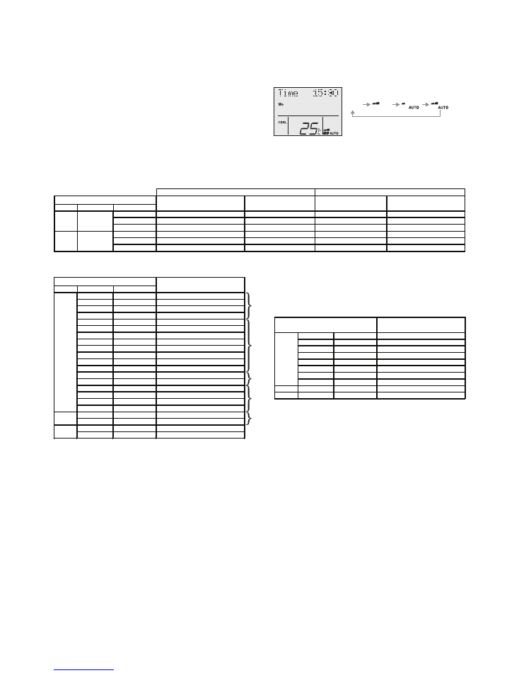
You have a choice of 5 temperature sensors.
1.) Indoor Sens – Temperature sensor located in the
indoor unit.
2.) Master RC - Master controller sensor
3.) Sub RC - When using option BRCSZC Sub controller.
4.) Sens 1 - When using option KRCSO1-1
5.) Sens 2 - When using option KRCSO1-1
Only the indoor sensor will be activated
(factory set) all other sensors must be activated by
the field set codes, once activated sensor selection
can be achieved by pressing the SEL SENSOR
button on the remote controller.
Temperature sensor activation
Zone restriction
Note 4.
Example: You may only require the use of 4 zones out
of the 8 available zones. By applying the Field setting
1b - 3 - 0_ you can restrict the number of zones you
want to operate, for example 4 zones. The remaining
unused zones will not function when the zone buttons
are pressed. ( 1b - 3 - 04 )
Before setting zone restriction make sure all zones are
switched off.
0
01
Sensor 1 OFF
1
01
Sensor 2 OFF
0
02
Sensor 1 ON
(Remote sensor KRCSO1-1 required)
1
02
Sensor 2 ON
(Remote sensor KRCSO1-1 required)
3
01
Zone 1 only
3
02
Zones 1-2
3
03
Zones 1-3
3
04
Zones 1-4
3
05
Zones 1-5
3
06
Zones 1-6
3
07
Zones 1-7
3
08
Zones 1-8
4
01
Keep 1 Zone ON
4
02
All Zones OFF
5
01
Master RC OFF
5
02
Master RC ON
6
01
Sub RC OFF
6
02
Sub RC ON
(Sub controller BRCZSC required)
6
01
Standard static pressure
(FDYQ(N)71-160 only)
6
02
High static pressure
(FDYQ(N)71-160 only)
3
01
Filter sign indication ON
3
02
Filter sign indication OFF
Set item
1b
Field Settings
Mode
Switch
Position
23
20
0
01
Sensor 1 OFF
1
01
Sensor 2 OFF
3
08
8 Zones available
4
02
All zones OFF
5
01
Master RC OFF
6
01
Sub RC OFF
2
01
Fan operation heating (Thermo off.)
7
01
Fan operation cooling (Thermo off.)
23
6
01
Standard static pressure
(FDYQ(N)71-160 only)
20
3
01
Filter sign indication ON
1b
Default Settings
Set item
Note 3.
Pg11
Note 4.
Pg11
Note 6.
Pg12
Note 3.
Pg11
Note 5.
Pg11
Fan static Pressure
Note 5.
When a higher airflow is required for example when the
pressure inside the ducting is high, use field setting
23-6-02 to increase the airflow.
For models with a capacity index of 180-250 please
refer to the installation instructions supplied with the air
conditioner.
Auto fan function with air sampling mode
Auto fan function will activate once the set point
temperature is achieved (thermo off) and will
deactivate when the room temperature is outside the
set point range (thermo on).
During Auto fan function the indoor fan will stop for a
period of 6 minutes and then start for a period of 30
seconds or more (depending on model) in order to
sample the room temperature.
Auto fan function will only activate when the “Indoor
Sens” (Indoor unit air temperature sensor) is selected.
Auto fan function will operate the same as Std. fan
function when other sensors are selected.
Fan operation during thermo. Off
Mode
Switch
Position
01
LL
OFF (Air sampling LL)
LL
OFF (Air sampling LL)
02
Set speed
OFF (Air sampling Set speed)
Set speed
OFF (Air sampling Set speed)
03
OFF
OFF (Air sampling OFF)
OFF
OFF (Air sampling OFF)
1
LL
OFF (Air sampling LL)
Set speed
2
Set speed
OFF (Air sampling Set speed)
Set speed
3
OFF
OFF (Air Sampling OFF)
Set speed
Set speed
Set speed
Set speed
Applies to models FDYQ(N)71FV1 & FDYQ(N)100-160KV1
Applies to models FDYQN200-250KV1 & FDYQ180-250MV1
1b
1b
2
Fan during heating
Std. Fan function
Auto fan function with
air sampling mode
7
Fan during Cooling
Std. fan function
Auto fan function with
air sampling mode
The table below indicates the possible Std. & Auto fan functions available during thermo off for heating & cooling,
please select the most appropriate fan function to suit the clients requirements.
Other field settings
Indoor fan settings
DS1 SWITCH
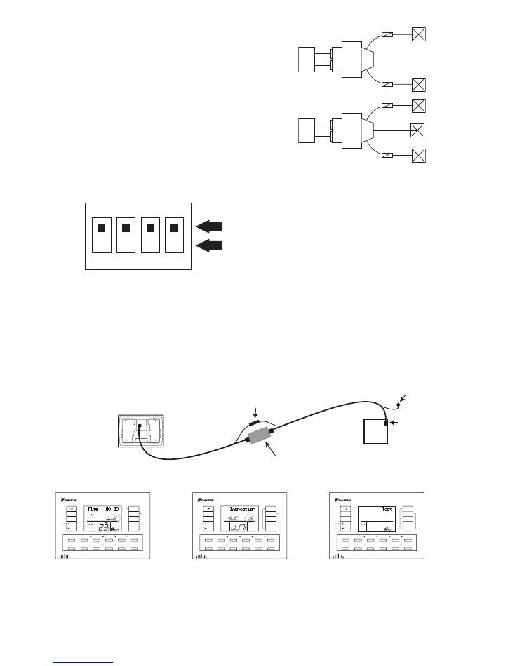
SW1 ON (Master controller) – When connecting one
remote controller only or when connecting two remote
controllers one controller must be selected to Master.
(Second controller is optional BRCSZC)
SW1 OFF (Sub controller) - When connecting two
remote controllers one controller must be selected to
Sub controller. (Second controller is optional BRCSZC)
SW2 Must remain in the ON position.
SW3 Must remain in the ON position.
SW4 ON (Start Up Delay Timer OFF)-The indoor fan
will start once the unit initialisation time is completed.
SW4 OFF (Start Up Delay Timer ON)-The indoor fan
will not start until at least 60 seconds has passed.
It is advisable when using spring return zone motors to
set SW4 OFF this will allow at least 60 second for the
zone motor to open before the indoor fan starts.
DS1 SWITCH
SW1 - ON = Master controller
SW1 - OFF = Sub controller
SW2 - No Function
SW3 - No Function
SW4 - ON = Start Up Delay Timer OFF
SW4 - OFF = Start Up Delay Timer ON
12
DS1
1
2
3
4
ON
OFF
Note 6.
Layout 1 (No Common Zone)
It is recommended to set the field set code to “Keep 1
Zone ON” One zone will remain on at all times when the
air conditioning unit is in operation to ensure damage to
the ducting system will not occur by over pressurising.
(1b - 4 - 01)
Layout 2 (Common Zone)
You can set “All Zones OFF” You will be able to
manually switch all the zones off if required.
(1b - 4 - 02)
ZONE 1
ZONE 2
ZONE 1
COMMON
ZONE 2
Duct Configuration
Back of controller
S8
Interface
PCB
Earth post
Earthed shield link
Adapter
How To Connect BRCW902A15 Extension Cable
(Optional Accessories)
DS1 Switch Settings
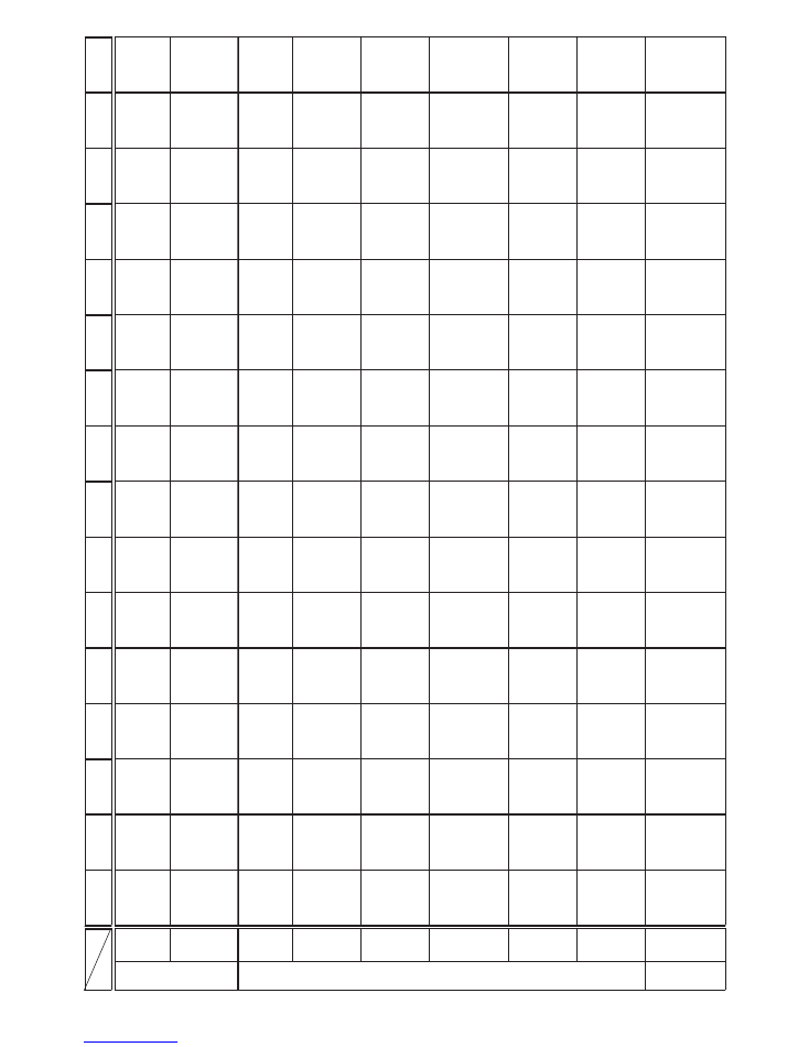
A two-digit code will flash on the
LCD screen when a fault occurs.
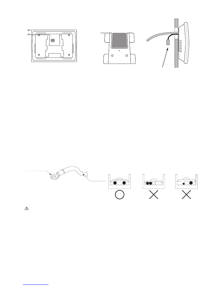
(Brief description of fault codes can
be found on Pg. 13.)
The inspection display will appear
once the TEST/EXIT button is
pressed. The inspection screen will
store the last fault code. To clear
the fault code press the clear
button for 4 seconds or until 00
appears. There are some fault
codes that will clear if the power is
switched OFF and then back ON again.
To enter the test mode press the
TEST/EXIT button twice. During the
test mode the system will be forced
to function according to the mode
set. The compressor will be forced to
operate for 30 minutes.
Fault Mode
Inspection Mode
Test Mode
MODE
FAN
TEMP
ADJUST
BUTTON
TEMP
SHIFT
7 DAY
TIME CLOCK
ON/OFF
TIMER
ENTER
CLEAR
TEST/EXIT
DAY TIME
ZONE1
ZONE2
ZONE3
ZONE4
SEL SENSOR
FIX SENSOR
ZONE5
ZONE6
ZONE7
ZONE8
MODE
FAN
TEMP
ADJUST
BUTTON
TEMP
SHIFT
7 DAY
TIME CLOCK
ON/OFF
TIMER
ENTER
CLEAR
TEST/EXIT
DAY TIME
ZONE1
ZONE2
ZONE3
ZONE4
SEL SENSOR
FIX SENSOR
ZONE5
ZONE6
ZONE7
ZONE8
MODE
FAN
TEMP
ADJUST
BUTTON
TEMP
SHIFT
7 DAY
TIME CLOCK
ON/OFF
TIMER
ENTER
CLEAR
TEST/EXIT
DAY TIME
ZONE1
ZONE2
ZONE3
ZONE4
SEL SENSOR
FIX SENSOR
ZONE5
ZONE6
ZONE7
ZONE8
Layout 1
Layout 2
13
0
1
2
3
EF
89
AH
Fa
n
in
te
rlo
ck
(ma
nua
l)
Ad
nor
ma
l
dra
in
wa
te
r
le
ve
l o
r p
lu
g
mi
ss
in
g
CJ
45
67
In
su
ffic
ient
wa
te
r s
upply
Dr
ain
le
ve
l
ab
ov
e
limi
t
AC
inpu
t ov
er-
cur
re
nt
Fa
ul
ty
el
ec
tron
ic
ex
pa
ns
io
n
va
lve
He
at
er
ov
er
hea
tin
g
Fau
lty
o
r di
rty
air
cl
ea
ne
r
E
H
No
load
up
Fa
ul
ty
ca
pa
ci
ty
se
ttin
g
Adn
or
ma
l h
ea
t
ex
ch
an
ger
(1)
tem
p.
Ad
no
rm
al
he
at
ex
cha
nge
r (
2)
te
mp
.
Fa
n
mo
to
r
ove
rloa
d ov
er-
cu
rre
nt
lo
ck
Ai
r d
ire
cti
on
adjus
t m
ot
or
lo
ck
Ac
tiv
ati
on of
saf
et
y de
vic
e
(g
en
er
al)
Fa
ul
ty
PC
B
In
do
or
INDOOR
OUTD
OOR
Fa
ul
ty
se
ns
or
sy
stem
(g
ener
al
)
U
F
J
L
P
A
C
Fa
ul
ty
dr
ain
wa
te
r le
ve
l
se
ns
or
sy
stem
Fa
ul
ty
heat
ex
ch
ange
r
te
mp
. se
ns
or
sy
stem
(R
2T
)
Fa
ul
ty ga
s
pipe
te
mp
.
sen
so
r sy
stem
(R
3T)
Fa
n
mo
to
r
ov
er
lo
ad
ov
er
-
cu
rre
nt, fa
ul
ty
lo
ck
se
ns
or
sy
stem
Ai
r d
irec
tion
m
oto
r lo
ck
,
fa
ul
ty se
nso
r
sys
te
m
Fa
ult
y AC
in
pu
t
cu
rren
t s
en
so
r
Fa
ul
ty a
ir
su
cti
on
te
mp
.
se
nso
r sy
stem
(R1
T)
Fa
ult
y ai
r
su
ct
io
n
te
mp
.
se
ns
or s
ys
te
m
Fault
y or
di
rty
se
ns
or
Fa
ul
ty
hum
idit
y
se
ns
or
sy
stem
Faul
ty te
mp
.
sens
or
(re
mo
te
co
nt
ro
lle
r)
Faul
ty
ra
diat
ion
sens
or
sy
stem
Faul
ty
high
pr
essu
re
swit
ch
Ac
tiva
tio
n o
f
sa
fe
ty dev
ic
e
(g
ener
al
)
Fa
ult
y PC
B
out
do
or
Ab
no
rma
l h
ig
h
pre
ssu
re
(HP
S)
Co
m
pre
ss
or
m
ot
or
ov
er
lo
ad
Co
mp
re
sso
r
mo
to
r ov
er-
cu
rre
nt
lo
ck
Ab
no
rm
al
lo
w
pr
es
su
re
(LP
S)
Ou
t d
oor
fa
n
mo
to
r ov
er
lo
ad
ov
er
-c
urr
en
t
lo
ck
AC
in
pu
t o
ver
-
cu
rre
nt
Fa
ul
ty
el
ec
tron
ic
ex
pa
nsi
on
va
lve
Pu
mp
ov
er
-
cur
re
nt
lo
ck
Ad
nor
ma
l
wa
te
r te
mp
.
Ac
tiva
tion
of
field add
ed
sa
fe
ty
de
vice
Faul
ty
dr
ain
wa
te
r le
ve
l
sy
stem
Fa
ul
ty h
eat
stor
age uni
t
Fa
ul
ty
se
nso
r
sy
stem
(g
ener
al
)
Fa
ul
ty
ai
r
te
mp
. se
ns
or
sy
stem
Fau
lty p
ow
er
suppl
y se
ns
or
sys
te
m
Fa
ult
y h
ig
h
pr
es
su
re
sw
itc
h
Fau
lty
lo
w
pre
ss
ure
sw
itch
Com
pr
esso
r
mo
to
r fa
ult
y
ov
erl
oa
d
se
ns
or
sy
stem
Co
m
pr
es
so
r
mo
to
r ov
er
-
cu
rre
nt
lo
ck
fa
ult
y s
ens
or
sy
stem
Abn
or
m
al
ou
td
oo
r fa
n
mo
to
r si
gn
al
Faul
ty
AC
in
pu
t
po
we
r se
ns
or
sy
stem
Fa
ult
y o
ut
door
air
te
mp
.
sen
so
r sy
stem
Fa
ult
y
dis
ch
arge ai
r
te
mp
. s
ens
or
sy
ste
m
Pu
m
p
ov
er
-
cu
rre
nt
lo
ck
fa
ult
y se
nso
r
sy
stem
Fa
ul
ty
ho
t
wa
te
r se
ns
or
sy
stem
Fa
ul
ty
dr
ain
wa
te
r le
ve
l
se
ns
or
sy
stem
Heat
st
or
age
un
it alar
m
Ac
tiv
ati
on o
f
co
mm
on
sa
fe
ty dev
ic
e
fo
r sy
ste
m
No
.
1
&
No.
2
Ac
tiva
tion
of
sa
fet
y d
evi
ce
fo
r sy
ste
m
No
.
1
Ac
tiva
tion
of
sa
fe
ty d
ev
ic
e
fo
r s
ys
te
m N
o.
2
Fa
ul
ty
dis
cha
rg
e pi
pe
te
mp
.
Re
frig
er
an
t
ov
erc
ha
rg
e
Adn
or
ma
l
dis
ch
ar
ge
pre
ss
ur
e
Ad
no
rm
al
hi
gh
oil
te
mp
.
Adno
rm
al
su
cti
on
pre
ss
ure
Ad
nor
ma
l oil
pr
es
su
re
Adno
rm
al
su
rfac
e
oil
le
ve
l
Fa
ult
y
ref
rige
ra
nt
te
mp
. se
ns
or
sy
ste
m
Fa
ult
y
pr
es
su
re
se
nso
r s
ys
te
m
(g
ene
ra
l)
Fa
ult
y cu
rren
t
se
ns
or
sy
ste
m
Fa
ul
ty
di
sc
ha
rg
e p
ip
e
te
m
p.
se
nso
r
sy
stem
Fa
ult
y lo
w
pre
ss
ur
e
eq
uiv
alen
t
sa
tu
ra
tio
n
tem
p.
se
nso
r
sy
ste
m
Fa
ul
ty su
cti
on
pi
pe
te
mp
.
se
nso
r sy
stem
Fa
ul
ty h
ea
t
ex
change
r
te
mp
. se
nso
r
sy
stem
(R
4T
)
Fa
ult
y r
ec
ei
ver
ou
tle
t liq
ui
d
pip
e s
en
sor
(R
7T
)
Fa
ult
y liq
uid
pip
e
te
m
p.
se
nso
r sy
stem
Fau
lty
su
bc
oo
ler
h
ea
t
exc
ha
nge
r ga
s
pipe
sen
so
r
(R
5T
)
Fa
ult
y
dis
cha
rg
e
pre
ss
ure
se
nso
r sy
stem
Fault
y o
il
te
mp
. se
nso
r
sys
te
m
Fa
ult
y su
ct
io
n
pre
ssu
re
se
ns
or
sy
stem
Fa
ul
ty o
il
pr
es
sur
e
se
ns
or
sys
te
m
Fa
ul
ty su
rfa
ce
oil le
vel
sen
sor
sy
ste
m
Fa
ul
ty IN
V
sy
stem
Fa
ul
ty
PC
B
Adn
orm
al
te
mp
. r
ise
in
side
c
on
tro
l
bo
x
Ad
no
rm
al
te
m
p.
ri
se
o
f
ra
dia
tion
fin
(po
we
r
transi
stor
)
DC
ou
tp
ut o
ver
-
cur
ren
t-
in
sta
nt
an
eo
us
AC
ou
tp
ut
ove
r-
cur
re
nt
-
in
sta
nta
ne
ou
s
Air
co
nd
itio
ner
(mu
lti)
ge
ne
ra
l
in
pu
t o
ve
r-
cur
ren
t
In
ve
rte
r c
urr
en
t
ab
no
rma
l
In
ve
rte
r st
ar
t-
up
er
ror
Fa
ult
y po
we
r
tran
sis
to
r
Fau
lty
tran
sm
iss
ion
be
tw
ee
n IN
V
and c
on
tro
l
PC
B
G
as
sh
or
ta
ge
(ice
th
erm
al
sto
ra
ge
eq
uipm
ent
)
High
vo
ltag
e
of
cap
ac
itor
in
in
ve
rte
r ci
rc
uit
or
po
we
r
im
ba
la
nc
e
Fau
lty
te
mp
.
ris
e
se
ns
or
in
side
co
nt
ro
l
bo
x
Fa
ult
y
ra
dia
tion
fin
(p
ow
er
tran
sist
or
)
te
mp
. ri
se
Fa
ul
ty
DC
cu
rre
nt
se
ns
or
sy
stem
Fau
lty
AC
o
r
DC
ou
tp
ut
cu
rren
t se
ns
or
sy
ste
m
Air
co
nd
itio
ner
(mu
lti)
ge
ner
al
inpu
t ov
er
-
cu
rre
nt
Fa
ilu
re
o
f
transm
issi
on
bet
we
en
ind
oo
r and
ou
td
oo
r unit
s
Fa
ul
ty
tran
sm
issi
on
be
tw
een
in
doo
r uni
t a
nd
re
mo
te
co
nt
ro
lle
r
Fa
ul
ty
tran
sm
iss
io
n
bet
ween
in
door
unit
s
(m
ai
n
&
su
b)
Sh
or
t o
f g
as
Re
ver
se
d
ph
as
e
co
nn
ec
tion
Fa
ul
ty p
ow
er
su
pply
vo
ltage
Fa
ult
y
tran
sm
issi
on
(gener
al
) or
ch
ec
k
oper
ati
on
is
no
t co
mp
le
te
Im
pr
op
er
co
mb
in
ati
on o
f
in
doo
r &
ou
td
oo
r,
in
do
or
&
re
mo
te
c
on
t.
Fa
ul
ty
ca
pa
ci
ty
set
ting
SYSTE
M
In
co
rre
ct
wir
ing
/p
ip
ing
(w
iri
ng
/p
iping
co
nnec
tion
erro
r)
In
do
or
/o
ut
do
or
un
it ad
dr
es
s
no
t en
te
re
d
Fa
ult
y c
ent
ra
l
con
tro
l
addr
ess
se
tting
(A
dd
re
ss
dupl
ica
tion
s)
Faul
ty
tran
sm
issi
on
to
/fr
om
pe
rip
her
al
equipm
en
t (a
ir
cont
ro
l
Faul
ty
tran
sm
issi
on
be
tw
een
indoor
uni
t and
ce
nt
ra
l
co
nt
ro
lle
r
Fa
ult
y
tra
ns
mi
ss
io
n
be
tw
ee
n
ou
td
oo
r unit
s
Fa
ult
y
tra
nsm
issi
on
to
/fr
om
re
m
ot
e
co
nt
ro
lle
rs
(m
ain
&
su
b)
Fa
ult
y
tra
ns
mi
ss
io
n
be
tw
een
indoor
&
ou
td
oo
r in
th
e
sa
me
sy
stem
Co
nte
nts
Co
de
Sec
tio
n
Co
de
14
Round crimp-style
terminal
Electric wire
PRECAUTIONS
Precaution for wiring on site
Do not clamp remote controller cords together with wires connecting the units together. Doing so may cause malfunction.
Remote controller cords and wires connecting the units should be located at least 50 mm from other electric
wires. Failure to follow this guideline may result in malfunction due to electrical noise. Read the notes mentioned
below when wiring to the power supply terminal block. Precautions to be taken for power supply wiring. (Use a
round crimp-style terminal for connection to the power supply terminal block. In case it cannot be used due to
unavoidable reasons, be sure to observe the following instructions.)
Do not connect wires of different gauge to the same power supply terminal. (Looseness in the connection may
cause overheating.)
When connecting wires of the same gauge, connect them according to the figure.
Make certain that prescribed wires are used, carry out complete connections, and secure the wires so that
outside forces are not applied to the terminals.
CAUTION
After connecting the wires, be sure that no pressure is applied to the wire connections by using cable ties (field
supplied) and securing them to the anchor points. Also, when wiring, make sure the cover of the terminal box fits
snugly by arranging the wires neatly and attaching the terminal box cover firmly. When attaching the terminal box
cover, make sure no wires get caught under the edges.
Make sure the remote control cord, the wiring between the electrical boxes, and other electrical wiring do not pass
through the same locations outside the unit, separating them by at least 50 mm, otherwise electrical noise
(external static) could cause interference to the control system.
All field supplied parts and materials and electric works must conform to local codes. (ie. AS / NZS 3000)
Use copper wire only.
For electric wiring work, refer also to the "WIRING DIAGRAM" label attached to the electrical box cover.
For remote controller wiring details, refer to this installation manual.
All wiring must be performed by an authorised electrician in accordance with local codes. (ie. AS / NZS 3000)
A circuit breaker capable of shutting down power supply to the entire system must be installed.
Ensure that the air conditioner and zone controller box are effectively earthed.
CORRECT
WRONG
WRONG
Connect wires of
the same gauge to
both sides
Do not connect
wires of the same
gauge to one side
Do not connect
wires of different
gauges
ELECTRIC WIRING WORK
CONTROLLER MOUNTING BRACKET
18mm
Hole flush
with
top of
bracket
HOLE
IN
WALL
Installed controller height 18mm
above top of mounting bracket.
Do not cut hole above height of
bracket.
Earth shield spade receptacle is
used only when extension cable
(BRCW902A15) is installed. When
BRCW902A15 is not used tuck
insulated spade receptacle in wall
cavity
1. Insert one end of P1/P2 harness into socket S9 located on the lower interface
PCB (A1P). Diagram 1.
2. Loosen (4) plastic nuts. Diagram 2.
3. Screw in (4) PCB post and gently tighten. Diagram 3
4. Install upper Interface PCB (A2P) in the same direction as lower Interface
PCB (A1P). Diagram 4.
5. Add (4) plastic nuts and gently tighten. Diagram 4.
6. Plug the loose end of P1/P2 harness into socket S7 of upper Interface PCB
(A2P). Diagram 4.
7. Wire Power harness into LN terminal block X3M (Black- L)
(White –N) (Green – Earth). Diagram 5.
8. Plug the other end of the power harness into S1 socket of the upper Interface
PCB (A2P). Diagram 5.
9. Pass the Remote controller cable through the 2 open cable ties. If the cable
ties have already been tightened cut the cable ties and use the spare cable
ties supplied to secure the controller leads. Diagram 7.
10. Plug the remote controller cable connector into socket S8 of upper Interface
PCB (A2P). Diagram 6.
11. Secure the earth shield to the earth shield post. Diagram 7.
TO REMOTE CONTROLLER
TO RELAY PCB S19 (8 ZONE ONLY)
TO RELAY PCB S19 (4 ZONE)
A2P
A1P
L N E
S12
S7 S9
S2
S1
S1
S3
S13
S12
S13
S8
TN1
(NOTE 2)
TN2
S7 S9
S2
S3
S8
TO SUB CONTROLLER
TN1
TN2
TO P1 P2 TERMINAL
BLOCK (NOTE1)
B
W
G X3M
Sub Controller Instructions BRCSZC
S9
S9
S9
S9
S1
L N
S7
1
2
3
4
5
6
7
S9
S8
L N
ACCESSORIES
CABLE
TIE
X 5
SUB ZONE
KEYPAD
X 1
P1/P2
HARNESS
X 1
POWER
HARNESS
X 1
PCB
POST
X 4
INTERFACE
PCB X 1
15M
CONTROLLER
CABLE
X 1
Remote controller wiring
A N E
A N E
S7
MODE
FAN
TEMP
ADJUST
BUTTON
TEMP
SHIFT
7 DAY
TIME CLOCK
ON/OFF
TIMER
ENTER
CLEAR
TEST/EXIT
DAY TIME
ZONE1
ZONE2
ZONE3
ZONE4
SEL SENSOR
FIX SENSOR
ZONE5
ZONE6
ZONE7
ZONE8
MODE
FAN
TEMP
ADJUST
BUTTON
TEMP
SHIFT
7 DAY
TIME CLOCK
ON/OFF
TIMER
ENTER
CLEAR
TEST/EXIT
DAY TIME
ZONE1
ZONE2
ZONE3
ZONE4
SEL SENSOR
FIX SENSOR
ZONE5
ZONE6
ZONE7
ZONE8
4PDA0687
NOTE:
1.
P1 P2 TERMINAL BLOCK
LOCATED IN THE ELECTRICAL
BOX OF INDOOR UNIT.
2.
TN1, TN2 ONLY USE DAIKIN
REMOTE TEMPERATURE
SENSOR KRCSO1-1
3. :TERMINAL
:CONNECTOR
4.
SYMBOLS SHOW AS FOLLOWS
B: BLACK
W: WHITE
G: GREEN
A1P INTERFACE PRINTED CIRCUIT BOARD
A2P INTERFACE PRINTED CIRCUIT BOARD
TN1 REMOTE SENSORS 1
TN2 REMOTE SENSORS 2
S1
S9-S7
S7
S8
CONNECTOR
230~240V
A1P 7 A2P COMMUNICATION
A1P INDOOR COMMUNICATION
REMOTE CONTROLLER
A1P
A2P
X3M
SCREW
X 2
MOUNTING
BRACKET
X 1
INSTALLATION
INSTRUCTION
X 1
1. Insert one end of P1/P2 harness into socket S9 located on the lower interface
PCB (A1P). Diagram 1.
2. Loosen (4) plastic nuts. Diagram 2.
3. Screw in (4) PCB post and gently tighten. Diagram 3
4. Install upper Interface PCB (A2P) in the same direction as lower Interface
PCB (A1P). Diagram 4.
5. Add (4) plastic nuts and gently tighten. Diagram 4.
6. Plug the loose end of P1/P2 harness into socket S7 of upper Interface PCB
(A2P). Diagram 4.
7. Wire Power harness into LN terminal block X3M (Black- A)
(White –N) (Green – Earth). Diagram 5.
8. Plug the other end of the power harness into S1 socket of the upper Interface
PCB (A2P). Diagram 5.
9. Pass the Remote controller cable through the 2 open cable ties. If the cable
ties have already been tightened cut the cable ties and use the spare cable
ties supplied to secure the controller leads. Diagram 7.
10. Plug the remote controller cable connector into socket S8 of upper Interface
PCB (A2P). Diagram 6.
11. Wire the controller lead earth shield cable to the earth shield post. Diagram 7.
TO REMOTE CONTROLLER
TO RELAY PCB S19 (8 ZONE ONLY)
TO RELAY PCB S19 (4 ZONE)
A2P
A1P
L N E
S12
S7 S8
S2
S1
S1
S3
S13
S12
S13
S8
TN1
(NOTE 2)
TN2
S7 S8
S2
S3
S8
TO SUB CONTROLLER
TN1
TN2
TO P1 P2 TERMINAL
BLOCK (NOTE1)
B
W
G X3M
Sub Controller Instructions BRCSZC
S9
S9
S9
S9
S1
A N
S7
1
2
3
4
5
6
7
S9
S8
A N
ACCESSORIES
CABLE
TIE
X 5
SUB ZONE
KEYPAD
X 1
P1/P2
HARNESS
X 1
POWER
HARNESS
X 1
PCB
POST
X 4
INTERFACE
PCB X 1
15M
CONTROLLER
CABLE
X 1
Remote controller wiring
A N E
A N E
S7
MODE
FAN
TEMP
ADJUS
T
BUT
TON
TEMP
SHIFT
7 DA
Y
TIME CLOC
K
ON/OFF
TIMER
ENTE
R
CLEA
R
TEST/EXI
T DAY TIME ZONE1
ZONE2
ZONE3
ZONE
4
SEL
SENSO
R FIX SENSO
R
ZONE5
ZONE6
ZONE7
ZONE
8
MODE
FAN
TEMP
ADJUS
T
BUT
TON
TEMP
SHIFT
7 DA
Y
TIME CLOC
K
ON/OFF
TIME
R
ENTE
R
CLEA
R
TEST/EXI
T DAY TIME ZONE1
ZONE2
ZONE3
ZONE
4
SEL
SENSO
R FIX SENSO
R
ZONE5
ZONE6
ZONE7
ZONE
8
4PDA0687
NOTE:
1.
P1 P2 TERMINAL BLOCK
LOCATED IN THE ELECTRICAL
BOX OF INDOOR UNIT.
2.
TN1, TN2 ONLY USE DAIKIN
REMOTE TEMPERATURE
SENSOR KRCSO1-1
3. :TERMINAL
:CONNECTOR
4.
SYMBOLS SHOW AS FOLLOWS
B: BLACK
W: WHITE
G: GREEN
A1P INTERFACE PRINTED CIRCUIT BOARD
A2P INTERFACE PRINTED CIRCUIT BOARD
TN1 REMOTE SENSORS 1
TN2 REMOTE SENSORS 2
S1
S9-S7
S7
S8
CONNECTOR
230~240V
A1P 7 A2P COMMUNICATION
A1P INDOOR COMMUNICATION
REMOTE CONTROLLER
A1P
A2P
X3M
SCREW
X 2
MOUNTING
BRACKET
INSTALLATION
INSTRUCTIONS
INST
ALLA
TION MANUAL
ZONE
CONTROLLER
Air
Conditioners
MODELS
BRC230Z4
BRC230Z8
BRC24Z4
BRC24Z8
BRCSZC
PLEASE
READ
THESE
INSTRUCTIONS
CAREFULL
YBEFORE I
NST
ALLA
TION.
KEEP
THIS M
ANUAL
IN A
HANDY
PLACE
FOR
FUTURE RE
FERENCE.

DAIKIN AUSTRALIA PTY. LIMITED
77-83 Alfred Road, Chipping Norton, NSW 2170 Australia
Phone: 1300 78 72 66
www.daikin.com.au
DAIKIN INDUSTRIES LTD.
Head office:
Umeda Centre Building, 4-12 Nakazaki-Nishi 2 chome,
Kita-ku, Osaka, 530-8323 Japan
Tokyo office:
Shinjuku Sumitomo Building, 6-1 Nishi-Shinjuku
2 chome, Shinjuku, Tokyo, 163-0290 Japan
4PDA0685