Full Text Searchable PDF User Manual
I-1205
Rev. B-43
Overvi
The DEMA®
dish machine
Warnin
816
ew
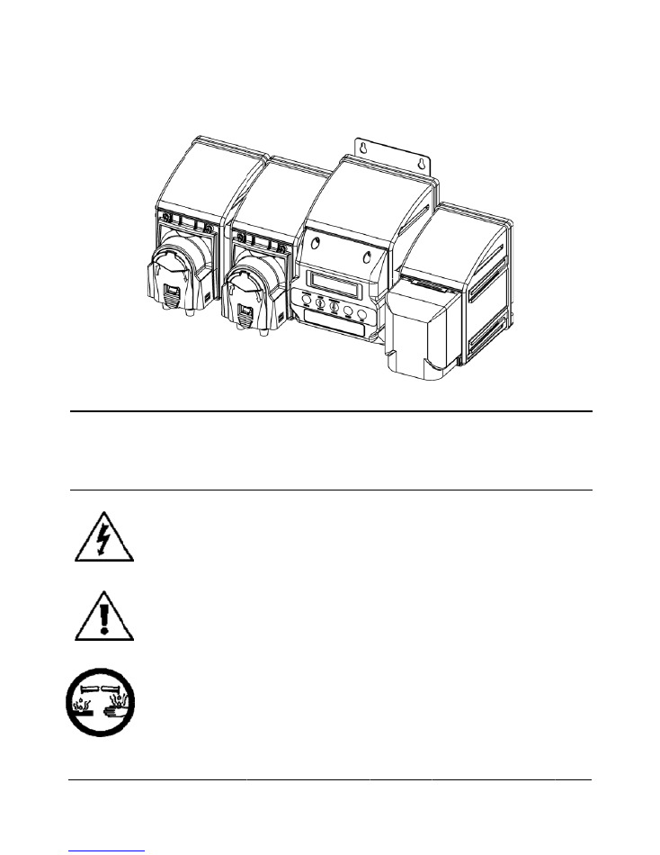
® Nitro Plus is
es. The unit is
ngs
Installati
by
nation
regulatio
installati
All
instal
devices.
codes
in
tee
.
ALWAYS
W
3/23/20
Ware W
s a digital ware
triggered by a
ion
of
DEMA
p
nal,
city,
count
ons
require
tha
on.
For
questio
lations
must
c
A
pressure
ind
the
state
of
W
WEAR
PROTEC
018
DEMA
Wash Ch
e wash dispense
ware wash ma
roducts
must
m
ty,
parish,
prov
at
a
certified
el
ons,
contact
a
onform
to
loca
dicating
tee
is
t
Wisconsin
and
a
TIVE
CLOTHING
A Nitro
hemical
er designed to
achine. The Nit
meet
all
applic
vincial
or
other
lectrical
contra
certified
elect
al
plumbing
co
to
be
installed
any
other
state
G
AND
EYEWEA
Plus
Dispens
dispense clean
tro Plus is prog
cable
electrical
r
agencies.
It
is
actor
or
engine
rician.
des
and
use
ap
with
existing
f
e
that
requires
AR
WHEN
WO
Page
sing
ning chemicals
grammed via th
codes
and
reg
s
possible
that
eer
perform
th
pproved
backf
faucets
accord
the
use
of
a
p
ORKING
WITH
C
1 of 13
into ware was
he front panel.
gulations
estab
electrical
code
e
electrical
low
prevention
ing
to
local
plu
ressure
indicat
CHEMICAL
PRO
sh and
blished
es
and
n
umbing
ting
ODUCTS.
I-1205
Rev. B-43816
Page 2 of 13
3/23/2018
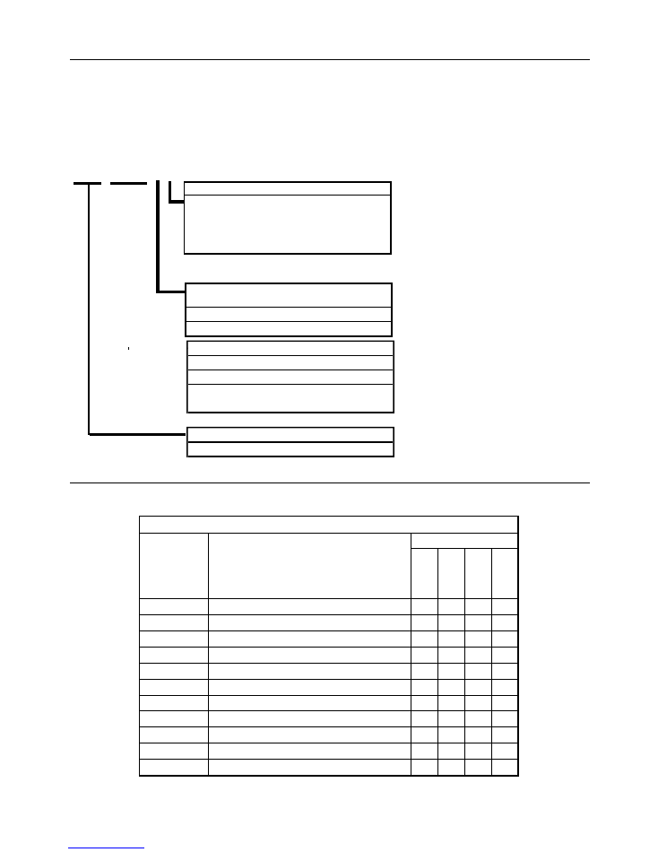
Note:Left to Right- 1st Position Detergent,
2nd Position Rinse, 3rd Position Sanitizer
L = Liquid (pump)
D = DRY (solenoid valve)
Liquid or Dry Chemical Product
Nitro Plus
Base Unit
Nitro Express Models
Nitro Plus can be built in a number of configurations. The following applies to all systems.
Prewired with power, trigger and probe cables.
Mounting bracket assembled to the Nitro Plus and ready to use.
Appropriate installation kit items that include, fittings, tubing, etc. (see Packout Kit section)
NP.DLL.TI
Trigger Device
T = Trigger Board
M = Magnetic Field Sensor
Packing Kit List
Nitro
Plus
Installation
Kit
Part
Number
Description
Qty/Model
NP.DL.T
NP.LL.T
NP.DLL.T
NP.LLL.T
904.8T
Rinse
Check
Valve
(Stainless
Steel)
1
1
1
1
904.8KY
Sanitizer
Check
Valve
(Kynar)
1
1
80.55
Liquid
Detergent
Bulkhead
Fitting
1
1
58.5
Dry
Detergent
Bulkhead
Fitting
1
1
C.12VIK
Conductivity
Probe
(Flip
Probe)
1
1
1
1
25.68.20
1/4"
OD
LDPE
Tubing
‐
20ft
1
1
1
1
100.12.SV1
Vinyl
Rinse
Tube
‐
16ft
1
1
2
3
81.312.1
Split
Pickup
Tube
Stiffener
1
2
2
3
81.182.1
1/4"
x
1/4"
Push
‐
On
Fittings
(for
pump)
2
4
4
6
81.16.1
Tie
Wraps
8"
Long
5
5
8
8
I
‐
1205
Instruction
Sheet
1
1
1
1
Strain Relief
System will come with strain relief for the
wiring that is exiting the enclosure.
Systems that do have the "I" come
with a 1/2" conduit.
I-1205
Rev. B-43816
Page 3 of 13
3/23/2018
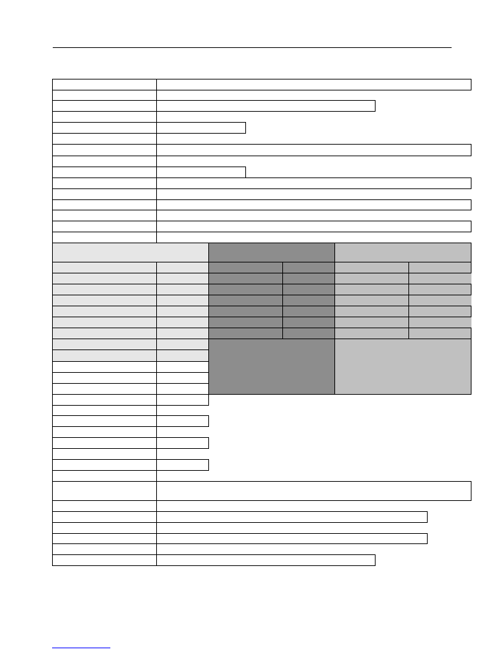
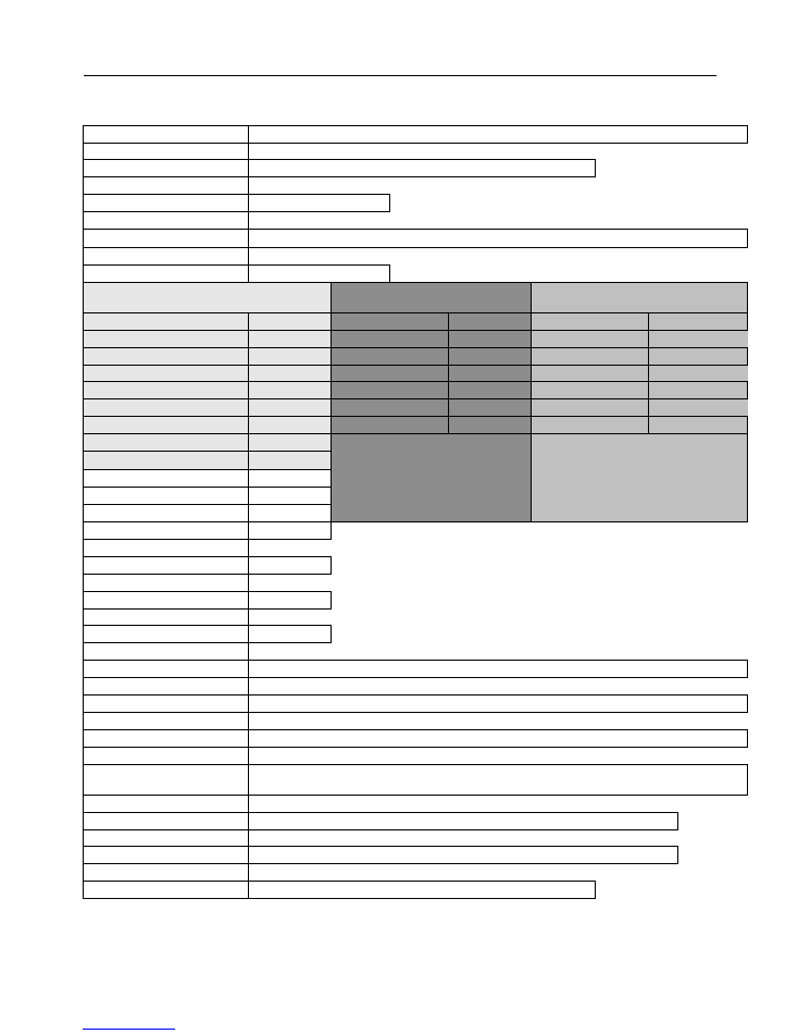
Operational Requirements
For Indoor Use Only
Main Power
100 VAC – 250 VAC 50/60 Hz 1.5 A
Trigger Signals
20V – 500V 50/60 Hz 200mA
Motors/Solenoid Valves
24VDC
Detergent Pump Rate
10oz/min (300ml/min)
Rinse/Sanitizer Pump Rate
0.5oz/min (15ml/min)
Operating Temp
4-30°C
40-100°F
Case Material
ABS
Weight
3.8 kg
8.5 lbs
Max. Altitude
2000 M
6500 ft
Environmental Temp
0-40°C
32-104°F
Installation Category
II
Pollution Category
II
The integrity and operational characteristics of this unit are not guaranteed outside the above
mentioned parameters. Use of this unit outside of these parameters nullifies warranty.
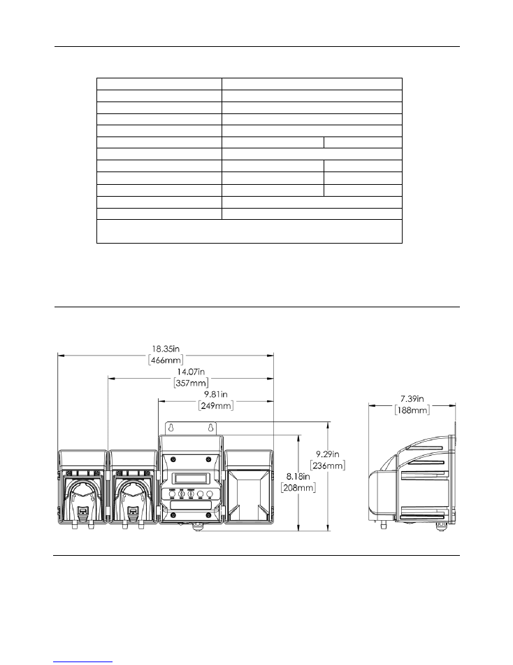
Overall Size
Sanitizer Rinse
Detergent

I-1205
Rev. B-43
Installa
ALL ELEC
MACHINE
UNIT MUS
Mounting th
1.
Det
pow
2.
Usi
Setting up t
1.
Loc
man
2.
Pro
3.
If th
12V
wat
inta
4.
Inst
read
5.
Inst
mac
6.
Inst
man
this
Connecting
1.
Aft
con
and
2.
Cut
che
3.
Me
4.
Cut
Wiring the N
The followin
The followin
dish machine
separately fr
to have powe
816
ation
WARNI
ELECT
COUNT
ELECT
ELECT
INSTAL
CTRICAL POW
PRIOR TO B
T BE GROUN
he Nitro Plus
termine a suitab
wer and trigger
ing the mountin
he Nitro Plus
cate the electric
nufacturer of th
perly ground th
he Nitro Plus w
VIK probe or th
ter level, norma
ake, drains and
tall the deterge
ding of all chem
tall the rinse lin
chine. If a tap i
tall the sanitize
nufacturer of th
s fitting.
the Chemical
er mounting th
ntainers. The de
d sanitizer tubin
t the tubing to t
emical containe
asure the lengt
t the tubing to t
Nitro Plus to t
ng diagram is in
WARNI
trigger s
manufac
UNIT M
ng steps will he
e that it is bein
rom the dish m
er to run the se
3/23/20
ING: INSTAL
RICAL CODE
TY, PARISH,
RICAL CODE
RICAL CON
LLATION. FO
WER MUST B
BEGINNING
NDED (EART
ble location tha
r signals. (Main
ng bracket han
and the Dish
cal connection
he machine to
he dispenser to
will be operatin
he DEMA Indu
ally 1-2” from
incoming wat
ent injection bu
micals entering
ne injection fitt
is not provided
er injection fitti
he machine. If
l Tubing to the
he dispenser, m
etergent tubing
ng (100.12.SV
the length requ
er.
th of tubing nee
the length requ
the Dish Mach
ncluded to help
ING: For safet
signals to the N
cturer’s recom
MUST BE GRO
elp to insure th
ng used in conju
achine. The fo
etup that is prog
018
LLATION OF
ES AND REG
PROVINCIA
ES AND REG
TRACTOR O
OR QUESTIO
BE TURNED
INSTALLAT
THED).
at will accomm
n power is typi
ng the Nitro Plu
Machine
point. The inp
determine if th
o earth ground.
ng in the conce
uctive Probe (8
the bottom of
er supply.
ulkhead fitting
g the wash tank
ting (904-8T) i
d, follow the ma
ing (904-8KY)
a tap is not pro
e Nitro Plus
measure the len
g (25.68.20) is
1) which is cle
uired and, if de
eded to go from
uired to reach th
hine
p to install the
ty purposes di
Nitro Plus. Co
mmendations.
OUNDED (EA
he proper wirin
unction with. D
llowing steps w
grammed in th
F DEMA PRO
GULATIONS
AL OR OTHER
GULATIONS
OR ENGINEE
ONS, CONTAC
OFF TO THE
TION
modate the leng
cally connecte
us using approp
put power may
here are dedicat
.
entration mode,
82.28.1) in the
the tank, and m
(80-55) above
k.
into the rinse li
anufacturer’s r
) (if sanitizer is
ovided follow t
ngth of tubing n
opaque in colo
ear in color and
sired, place the
m the dispenser
he bulkhead fit
wires in the co
isconnect mai
onnect power t
ARTHED).
ng of the unit. T
DEMA Engine
will insure that
he unit.
ODUCTS MUS
ESTABLISH
R AGENCIES
REQUIRE TH
ER PERFORM
CT A CERTI
E HEATING
gth of the prein
ed to a known s
priate screws a
be 100V – 265
ated terminals a
, locate the pro
wash tank. Th
must be kept aw
the probe (if a
ine tap provide
recommendatio
s used) into the
the manufactur
needed to go fr
or and has a lar
d has a small in
e pickup tube o
r to the chemic
tting or chemic
orrect places fo
in power to th
to the Nitro P
The unit should
eering does not
t the unit only
Page
ST MEET AL
HED BY NATI
S. IT IS POSS
HAT A CERT
M THE ELEC
IFIED ELECT
ELEMENTS
nstalled wiring
source in the d
and wall anchor
5 V 50/60 Hz.
available for ins
oper position fo
he probe must b
way from heati
a probe is used)
ed by the manu
ons for installin
e rinse line tap
rer’s recommen
rom the dispen
rger inside diam
nside diameter.
on the tubing b
cal injection po
cal injection po
or proper powe
e dish machin
Plus per the dis
d be triggered t
t recommend p
receives power
4 of 13
LL APPLICAB
IONAL, CITY
SIBLE THAT
TIFIED
CTRICAL
TRICIAN.
AND DISH
g for both the m
ish machine).
rs.
Check with th
stallation.
or the DEMA C
be installed bel
ing elements, p
) to obtain a ra
ufacturer of the
ng this fitting.
provided by th
ndations for ins
nser to the chem
meter than the
before placing i
oint on the mac
oint on the mac
er for the unit.
ne before wirin
sh machine
to power on fro
powering the un
r when it is nec
BLE
Y,
main
e
C-
low the
pump
apid
e
he
stalling
mical
rinse
in the
chine.
hine.
ng
om the
nit
cessary
I-1205
Rev. B-43816
Page 5 of 13
3/23/2018
Flux Sensors -
If trigger connection points cannot be established, the magnetic field readers (82.23.1) may be used in
place of the trigger board and cable. The magnetic field readers or flux sensors connect directly to the control board in
the trigger wires spots as shown on the wiring diagram. The magnetic field readers or flux sensors can be placed on
wash motors or rinse valves to measure a magnetic field when the motors or valves are activated which will trigger the
proper pump or valve on the dispenser.
1.
Connect the wash trigger (white and brown wires) to the appropriate wash trigger output (between 24 and 480
V 50/60Hz) as recommended by the dish machine manufacturer.
2.
Connect the rinse trigger (black and red wires) to the appropriate rinse trigger output (between 24 and 480 V
50/60 Hz) as recommended by the dish machine manufacturer.
3.
Make sure to connect the earth ground (green wire) to the ground connection on the dish machine as
recommended by the dish machine manufacturer.
Main Power should be applied any time there is power to the dish machine. The main power cable will come out of the
conduit fitting with the trigger cable and be hooked up near the same electrical connection point on the dish machine.
If there is ever any question about the main power or trigger cable connection to the dish machine, please check
with the dish machine manufacturer to see where the proper trigger connection points are located before
installing the trigger connection wires.
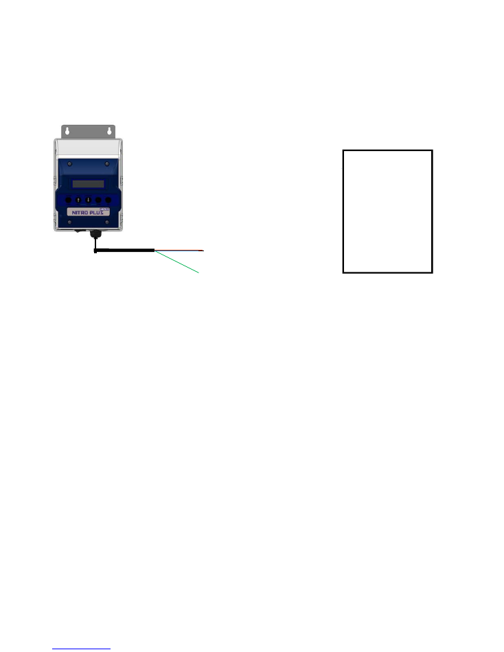
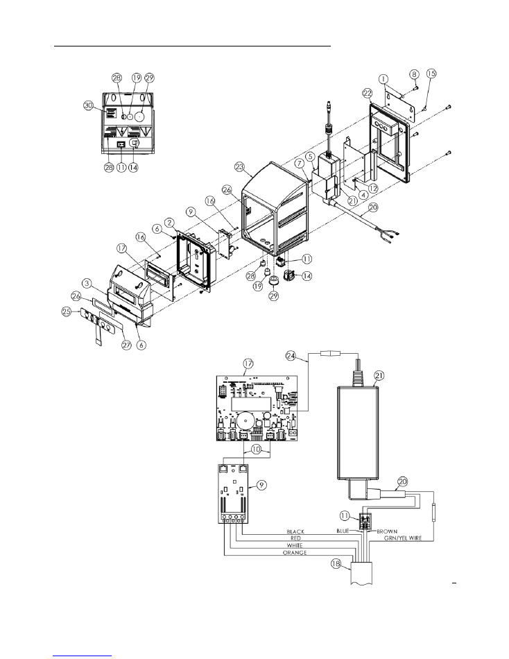
BROWN – MAIN POWER
BLUE – (LINE) MAIN POWER
ORANGE – WASH TRIGGER (HOT)
WHITE – WASH TRIGGER (RETURN)
BLACK – RINSE TRIGGER (HOT)
RED – RINSE TRIGGER (RETURN)
GREEN – EARTH GROUND
DISH MACHINE
ELECTRICAL
CONNECTION
POINT
I-1205
Rev. B-43816
Page 6 of 13
3/23/2018
Initial Programming
The programming of this unit is done through the control board, display, and buttons on the front of the unit.
Programming of the unit is as follows:
Company Name
Press and hold “Enter” Button for 3 Seconds until backlight comes on
Press
Language
English, Spanish, French, Portuguese
Press
Rack Count
Show Rack count
Press
Det. SP Input
Det. C = Concentration or P = Probeless SP= Set point Input & probe reading
Press
New Program
Press Enter
Control Mode
Press Enter, then select using arrows Concentration (Probe) or Probe-less
Press
Machine Type
Press Enter, then select using arrows Conveyor or Door
.
Press
Trigger Mode
Press Enter, then select Detergent/Rinse or Rinse Only or Detergent Only
Press
When Concentration is chosen
When Probeless Door is
chosen
When Probeless Conveyor is
chosen
Concentration Set Point
0-1000
Recharge Time
1s – 5 min
Recharge Time
1s – 5min
Press
Press
Press
Feed Rate
0-10
Dead Cycles
0-5
Dwell Time
1s – 10 min
Press
Press
Press
Feed Limit
5s – 10 min
Initial Charge
1s – 10 min
Initial Charge
1s – 10 min
Press
Press
Press
Alarm Delay
5s - 10 min
Charge Activate
Off-60s
Charge Clock
5 min – 16 hrs
Press
Initial Charge Activate
will
determine the length of the
rinse trigger that instigates an
initial charge while in probe-less
mode.
Charge Clock –
If no triggers are
received for this length of time, the
next wash trigger will give an initial
charge.
Alarm Volume
0-10
Press
Rinse Speed
0-100%
Press
Rinse Delay
0-15s
Door Mode Only
Press
Rinse Limit
15s - 30s
Door Mode Only
Press
Rinse Length
5s-75s
Conveyor and Door/Detergent Trigger only Modes
Press
Sanitizer Speed
0-100%
Press
Company Name
Press Enter, use arrows to change characters, use sanitizer prime and exit to move
cursor left and right.
Press
Rack Count
Press Enter, then Exit to Reset Rack Count
Press
Enter New Code
Enter 4 digit code, use sanitizer prime button to move cursor
Press
Control Mode
Reverts back to beginning of programming
Inductive Probe –
With the inductive probe there are a several settings that can be further changed to help make the
inductive probe more useful. For detailed information on those settings, please see instruction sheet I889 that comes
with the Inductive Probe Kit (82.28.1). For further assistance contact DEMA Technical Service.
I-1205
Rev. B-43816
Page 7 of 13
3/23/2018
Modify Programming
When modifying the programming of the unit. Use the flow chart below for modifications. The menus change slightly
when modifying the programming.
Company Name
Press and hold “Enter” Button for 3 Seconds until backlight comes on
Press
Language
English, Spanish, French, Portuguese
Press
Rack Count
Show Rack count
Press
Det. SP Input
Det. C = Concentration or P = Probeless SP= Set point Input & probe reading
Press
Modify Program
Enter Code
When Concentration is chosen
When Probeless Door is
chosen
When Probeless Conveyor is
chosen
Concentration Set Point
0-1000
Recharge Time
1s – 5 min
Recharge Time
1s – 5min
Press
Press
Press
Feed Rate
0-10
Dead Cycles
0-5
Dwell Time
1s – 10 min
Press
Press
Press
Feed Limit
5s – 10 min
Initial Charge
1s – 10 min
Initial Charge
1s – 10 min
Press
Press
Press
Alarm Delay
5s - 10 min
Charge Activate
Off-60s
Charge Clock
5 min – 16 hrs
Press
Initial Charge Activate
will
determine the length of the
rinse trigger that instigates an
initial charge while in probe-less
mode.
Charge Clock -
If no triggers are
received for this length of time, the
next wash trigger will give an initial
charge
Alarm Volume
0-10
Press
Rinse Speed
0-100%
Press
Rinse Delay
0-15s
Door Mode Only
Press
Rinse Limit
15s - 30s
Door Mode Only
Press
Rinse Length
5s-75s
Conveyor and Door/Detergent Trigger only Modes
Press
Sanitizer Speed
0-100%
Press
Control Mode
Press Enter, then select using arrows Concentration (Probe) or Probe-less
Press
Machine Type
Press Enter, then select using arrows Conveyor or Door
.
Press
Trigger Mode
Press Enter, then select Detergent/Rinse or Rinse Only or Detergent Only
Press
Company Name
Press Enter, use arrows to change characters, use sanitizer prime and exit to move
cursor left and right.
Press
Rack Count
Press Enter, then Exit to Reset Rack Count
Press
Enter New Code
Enter 4 digit code, use sanitizer prime button to move cursor
Press
Control Mode
Reverts back to beginning of programming
I-1205
Rev. B-43816
Page 8 of 13
3/23/2018
Replacement Parts and Reference Information

I-1205
Rev. B-43816
Page 9 of 13
3/23/2018
Nitro
Plus
Control
Module
Replacement
Parts
Item
No.
DEMA
Kit
No.
Description
1
81.1
Mounting
Bracket
Kit
(includes
2pcs,
81.19.1,
#8
Flat
Head
Screw)
2
81.501
Mounting
Panel
(for
trigger
board)
3
81.499
Control
Panel
Cover
4
84.500
Base
Bracket
(for
power
supply)
5
84.501
Cover
Bracket
(for
power
supply)
6
41.40.2
#6
‐
32
x
1/2"
Screw
7
41.69.2
#6
x
1/2"
SS
Sheet
Metal
Screw
8
44.116.2
#8
x
1/2"
Hi
Lo
Screw
(for
plastic)
9
81.118.11.2
Trigger
Board
Kit
10
81.118.12
Trigger
Cable
Kit
(trigger
board
to
control
board,
2pcs
in
kit)
11
81.163.1
Power
Switch
12
81.18.1
#6
x
3/8"
Hi
Lo
Screw
(for
plastic)
13
81.181.2
Probe
Cable
14
84.176.1
Strain
Relief
15
81.19.1
#8
Flat
Head
Screw
16
81.20.2
#4
x
3/8"
Hi
Lo
Screw
17
81.118.42
Nitro
Control
Board
18
81.320.4
Power/Trigger
Cable
Assembly
(external
power
&
trigger)
19
81.47.1
1/2"
Hole
Plug
20
84.125.4
Power
Supply
Cable
21
84.154.1
Power
Supply
115/230VAC,
24VDC,
2.5A
60W
22
84.195.3
Enclosure
Back
23
84.206.3
Enclosure
24
84.298.1
24VDC
Power
Adapter
(barrel
jack
to
modular
connector)
25
L1113
Membrane
Label
26
L1123
Display
Label
27
L1715
Nitro
Plus
Label
28
84.183.7
Cable
Strain
Relief
29
81.47.4
7/8"
Hole
Plug
30
L947
‐
4
Trigger
Wire
Colors
Label
I-1205
Rev. B-43
Item
N
1
2
3
4
5
6
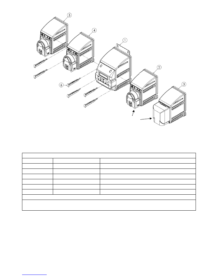
Nitro
Plus
Pump
Mod
sanitizer
c
816
Nitro
Plu
No.
Control
Mod
dule
Kits
inclu
heck
valves
a
3/23/20
us
Control
M
DEMA
Kit
81.118.
84.65.3
81.118.
81.118.
81.118.
81.144
ule
include
p
ude
side
mod
and
necessary
018
odule
Replac
t
No.
.43
32
.40
.41
.18
4.1
rewired
pow
ule
joints,
pre
y
pickup
and
d
cement
Kits
(
Nitro
Plus
C
Detergent
P
Detergent
V
Rinse
Modu
Sanitizer
Pu
Side
Modul
er
and
trigge
ewired
with
c
discharge
tub
Deterg
Deterge
includes
mod
D
Control
Modu
Pump
Module
Valve
Module
ule
Kit
ump
Module
K
e
Joint
r
cables
and
4
cable,
necess
bing.
gent Pump or
ent Valve type
Page
dule
mountin
Description
ule
e
Kit
e
Kit
Kit
4
side
module
ary
pump
or
10 of 13
ng
pins)
e
joints.
valve
fittings
,
rinse
or
I-1205
Rev. B-43816
Page 11 of 13
3/23/2018
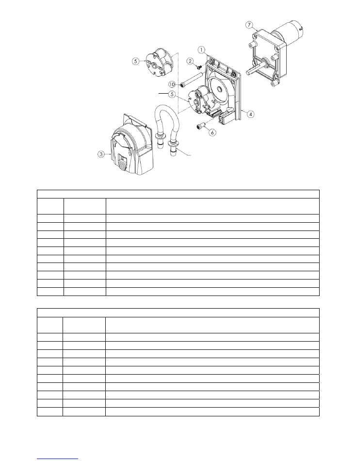
3 Roller Fixed – Roller Block
(Rinse/Sanitizer Pump)
Spring Loaded - Roller Block
(Detergent Pump)
Squeeze Tube
(See Common Replacement Parts on page 12)
Detergent
Pump
Parts
Item
No.
DEMA
Kit
No.
Description
1
81.173.12
Detergent
Pump
Assy
w/60
RPM
Motor
(no
enclosure)
2
41.40.2
#6
‐
32
x
1/2"
Stainless
Steel
Screw
3
81.174.1
Blue
Pump
Cover
4
81.128.2
Blue
Pump
Base
5
81.172.1
Spring
Loaded
Roller
Block
Assembly
6
25.85.2
#10
‐
32
x
1/2"
Stainless
Steel
Screw
7
80.59.60MK.1
60
RPM
Detergent
Pump
Motor
Kit
8
81.47.1
1/2"
Hole
Plug
(not
shown,
plugs
unused
1/2"
holes
on
back
of
enclosures)
9
81.118.15
Detergent
Pump
Kit
‐
Blue
Pump
Parts
&
Roller
Block
Assy,
no
motor
10
25.85.19
#10
‐
32
x
2"
Stainless
Steel
Screw
Rinse/Sanitizer
Pump
Parts
Item
No.
DEMA
Kit
No.
Description
1
81.173.7
Rinse/Sani
Pump
Assy
w/15
RPM
Motor
(no
enclosure)
2
41.40.2
#6
‐
32
x
1/2"
Stainless
Steel
Screw
3
81.174.1
Blue
Pump
Cover
4
81.128.2
Blue
Pump
Base
5
81.172.2
3
Roller
Fixed
‐
Roller
Block
Assembly
6
25.85.2
#10
‐
32
x
1/2"
Stainless
Steel
Screw
7
80.59.15MK.1
15
RPM
Rinse/Sanitizer
Pump
Motor
Kit
8
81.47.1
1/2"
Hole
Plug
(not
shown,
plugs
unused
1/2"
holes
on
back
of
enclosures)
9
81.118.16
Rinse/Sani
Pump
Kit
‐
Blue
Pump
Parts
&
Roller
Block
Assy,
no
motor
10
25.85.19
#10
‐
32
x
2"
Stainless
Steel
Screw
I-1205
Rev. B-43816
Page 12 of 13
3/23/2018
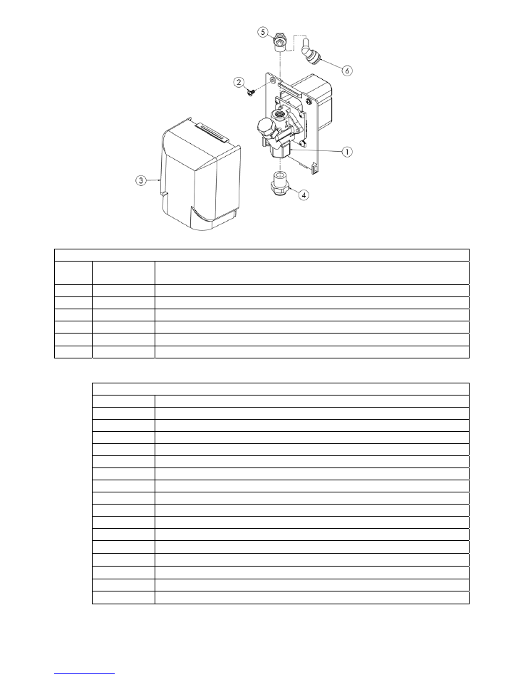
Detergent
Valve
Parts
Item
No.
DEMA
Kit
No.
Description
1
81.204.1
Detergent
Valve/Bracket
Assembly
2
41.40.2
#6
‐
32
x
1/2"
Stainless
Steel
Screw
3
81.146.1
Valve
Cover
4
58.103.2
1/4"
MPT
x
1/4"
Push
‐
On
JG
Fitting
5
58.104.3
1/4"MPT
x
1/4"
Push
‐
On
Elbow
JG
Fitting
6
81.195.1
1/4"
Stem
x
1/4"
Push
‐
On
Elbow
JG
Fitting
Squeeze
Tube
&
Common Replacement
Parts
DEMA
Kit
No.
Description
81.177.1
Squeeze
Tube
‐
Detergent
EPDM
‐
Default
squeeze
tube
with
Nitro
Plus
81.177.4
Squeeze
Tube
‐
Detergent
Silicone
81.177.2
Squeeze
Tube
‐
Rinse/Sani
EPDM
‐
Default
squeeze
tube
with
Nitro
Plus
81.177.22
Squeeze
Tube
‐
Rinse/Sani
Silicone
81.182.1
1/4"
x
1/4"
Push
‐
On
Union
JG
(connects
pickup
&
discharge
tubes
to
pump)
904.8T
Stainless
Steel
Rinse
Check
Valve
(not
suitable
with
chlorine
products)
904.8KY
Kynar
Sanitizer
Check
Valve
(suitable
with
chlorine
products)
80.55
Liquid
Detergent
Bulkhead
Fitting
58.5
Dry
Detergent
Bulkhead
Fitting
C.12VIK
Conductivity
Probe
(Flip
Probe)
25.68.20
1/4"
OD
LDPE
Tubing
‐
20ft
25.75
1/4"
OD
LDPE
Tubing
‐
100ft
100.12.SV1
Vinyl
Rinse
Tube
1/4"
OD
x
1/16"
ID
‐
16Ft
100.12.SV3
Vinyl
Rinse
Tube
1/4"
OD
x
1/16"
ID
‐
100Ft
81.312.1
Split
Pickup
Tube
Stiffener
81.17.5
Silicone
Grease
Pack
‐
1oz

I-1205
Rev. B-43816
Page 13 of 13
3/23/2018
Troubleshooting
(Some models may not include all items listed below)
Symptom Probable
Cause
Remedy
No power is being supplied
to the unit
1.
Trigger Cables connected to the wrong
place on the machine.
2.
Switch on bottom of unit is turned off.
3.
Power is not cycling on the machine
properly.
4.
Trigger/Power cable is damaged from
installation.
1.
Check wiring diagram for proper connection and
contact dish machine manufacturer for correct
trigger placement.
2.
Make sure switch is turned on.
3.
Check with the dish machine manufacturer if all
power should have been restored to the unit to see
if there is an issue with the machine.
4.
Turn power to the dish machine off and inspect the
cable for any possible damage done.
Pumps are not priming like
they should be or not
holding a prime
1.
Hole in the tubing from the chemical
container to the pump head.
2.
Hole in the squeeze tube in the pump
head.
3.
Fitting is not tight on the tubing
1.
Check the tubing from the chemical container to
the pump head for leaks by feeling the tubing for
chemical that has leaked out. Replace the tube if
necessary.
2.
Replace the squeeze tube after inspecting it for a
possible hole or leak.
3.
Check both the inlet and outlet fitting and tighten if
necessary to create a good seal.
Pump over feeding
1.
If in concentration or probe mode,
feed rate may not be set correctly.
2.
If in concentration or probe mode,
probe cable may not be connected
properly.
3.
If a probe is being used, scale could be
built up on the probe.
4.
Range of set point is too low.
1.
Check the programming for the feed rate.
2.
Check the probe cable connection points and make
sure it is connected properly.
3.
Clean Probe.
4.
Check set point in programming.
Pump under feeding
1.
If in concentration or probe mode, the
probe cable may be shorted.
2.
If a probe is being used, scale would
be build up on the probe.
3.
Range of set point is too high.
1.
Check the probe cable for any possible shorts and
correct the issue where necessary.
2.
Clean Probe.
3.
Check set point in programming.
Rinse/Sanitizer pump not
running
1. Speed turned off.
1. Check the programming to see the speed setting
and make sure it is on the proper setting.
Warranty
Merchandise Returns
No Merchandise will be Returned for Credit Without DEMA’S Written Permission. Returned Merchandise
Authorization Number is Required in Advance of Return.
Product Warranty
DEMA products are warranted against defective material and workmanship under normal use and service for
one year from the date of manufacture. This limited warranty does not apply to any products that have a
normal life shorter than one year or failure and damage caused by chemicals, corrosion, physical abuse, or
misapplication. Rubber and synthetic rubber parts such as “O”-rings, diaphragms, PVC tubing, and gaskets are
considered expendable and are not covered under warranty. This warranty is extended only to the original
buyer of DEMA products. If products are altered or repaired without prior approval of DEMA, this warranty is
void.
Defective units or parts should be returned to the factory with transportation prepaid. If inspection shows them
to be defective, they will be repaired or replaced without charge, F.O.B. factory. DEMA assumes no liability
for damages. Return merchandise authorization number must be granted in advance of returned units for repair
or replacement (See “Merchandise Returns” above).