Full Text Searchable PDF User Manual

EU
Declara on
of
Conformity
Cengar. Ltd.
Spring
fi
eld Works, Saddleworth Road
Halifax, England HX4 8LZ
We the undersigned, declare under our sole responsibility that the
following apparatus:
‐
Machine descrip on:
Cengar Air Saw
Machine Type:
CL50 & CL75
Is in conformity with the following relevant EC legisla on:
Machinery Direc ve
2006/42/EC
EN ISO 11148
‐
12:2012
‐
Handheld non
‐
electric power tools
EN ISO 13753: 2008
‐
Mechanical
Vibra on and shock
Atex Direc ve
2014/34/EU
Based on the following Harmonised Standards:
EN13463
‐
1:2009
And therefore complies with the essen al requirements of those
direc ves.
Addi onal Informa on:
ATEX Coding
II 2G T5 X
Technical filie lodged with:
Element Materials Technology (0891)
Technical File number:
CEEX-0803 (DIF039)
Authorised Signature:
Technical Manager
Roy Fletcher
Date:
02/11/16
Title of Signatory:
General Manager
‐
Cengar Ltd.
SPECIFICATIONS
Speed
Stroke
Air Consump on
Air Pressure
Weight
Length
Height
Width
Vibra on Level averaged
Sound Pressure Level
Sound Power Level
Atex Cer
fi
ca on
1200 strokes per minute
45 mm
0.168m
3
/minute
5
‐
6 Bar
2.5 Kgs.
400 mm.
135 mm.
40.6 mm.
3.2 m/s
2
82.9 db.
92.4 db.
CE II 2G T5 X
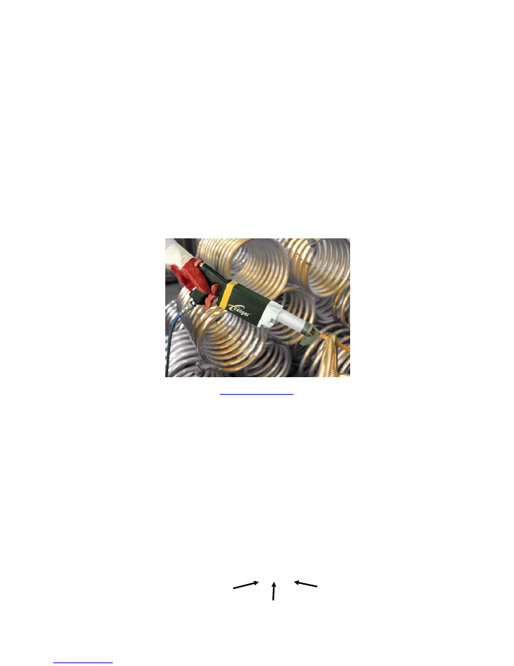
Cengar
Air
Saw
Models
CL
50
&
75
We recommend normal safe working prac ces
should be followed as per the Health and Safety at
Work Act. We recommend that Eye protec on be
worn when using Cengar Saws
We
recommend
normal
safe
working
prac ces
should
be
followed
as
per
the
Health
and
Safety
at
Work
Act,
or
the
appropriate
Na onal
and
State
Laws.
We
recommend
that
eye
and
ear
protec on
be
worn
when
using
Cengar
Saws
Each machine is marked with a unique serial number, which contains the year and month of
construc on, along with an iden
fi
er number.
Serial number example:
15 10 20
Year of construc on
Month of construc on
Iden
fi
er number

CENGAR
SAWS
are
hand
held
reciproca ng
saws
designed
to
cut
metals
and
plas cs
in
produc on
environments
and
can
be
used
in
Atex
zoned
areas
where
appropriate.
They
should
only
be
used
by
trained
operators
who
are
responsible
for
the
safety
of
themselves
and
others
in
the
vicinity.
Saw
blades
are
capable
of
causing
serious
injury
Think
safe
Act
safe
Be
safe
LUBRICATION
Use Cengar Green Oil with longer las ng coa ng proper es for best
results. Cengar Green Oil is specially prepared to:
‐
1
Emulsify the water generally found in compressed air lines.
2
Give perfect mist lubrica on.
3
Remain
fl
uid at the low working temperature of compressed air tools.
4
Contains corrosion and oxida on inhibitors.
Incorrect oils if used will soon “break down” forming a sludge which will
slow and eventually stop the ac on of the saw. See maintenance details.
INSTALLATION
OF
BLADES.
Before a emp ng to insert or change a blade, ensure that the air supply is
isolated by opera ng the isola on valve provided. Loosen the retaining
grub screws with the key provided, insert blade through nosepiece so that
the teeth are cu ng on the pull stroke.
Locate the back screw in the hole in the end of the blade, for a posi ve
drive, the front screw can then be ghtened to grip the blade
fi
rmly.
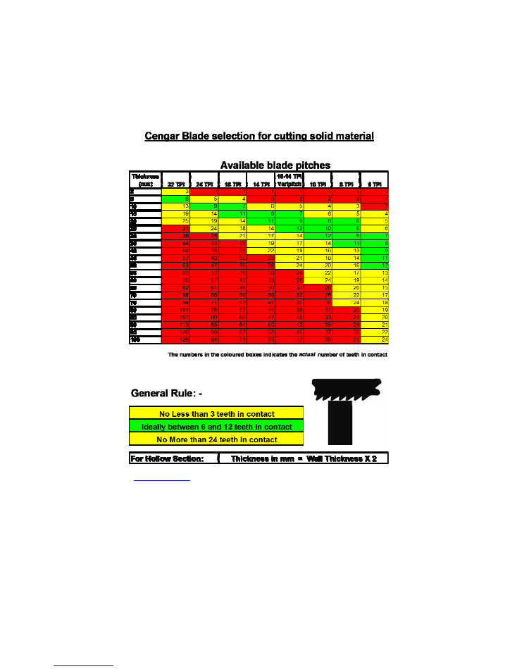
BLADES
Cengar “Sha erproof” Bi
‐
Metal blades are specially prepared for use with
Cengar saws, to withstand the high opera ng speeds, and give maximum
cu ng life.
Choose the teeth per inch to suit the characteris cs of the material being
cut.
Choose pitch to ensure that at least 3 or 4 teeth are cu ng at the same
me.
OPERATING
THE
SAW
We recommend that eye and ear protec on be worn, and normal safe working prac ces
observed as per the Health and Safety at work act, and the appropriate Na onal and State
Laws.
Set the isolator to “on” posi on, rest the blade on the material to be cut with the nosepiece
fi
rmly abu ed to the work piece, with forward hand pressure, to prevent judder. Allow the
Cengar Saw to cut under its own weight, with just a slight downward hand pressure to keep the
teeth engaged in the cut. It is not necessary to put excessive downward pressure on the saw,
this only accelerates blade wear, and prevents the saw from opera ng e
ffi
ciently. Normal
airline pressure of 5 to 6 Bar is required , any higher pressure only accelerates internal wear of
the machine.
WARNING/RISK
SPECIAL
CONDITIONS
FOR
SAFE
USE
1. Suitably approved Sta c dissipa ng or conduc ve air hose only to be a ached to
the equipment and terminated to the air supply
2. Operator to ensure that there is less than 1 Ohm resistance between the ground at
the air source and any metallic object to be cut with the equipment
3. The Saw shall be
fi
rmly abu ed to the work piece before opera on and quenched
with liquid during opera on
The saw is
HUMAN
OPERATOR
CONTROLLED
and THE
OPERATOR
MUST
ENSURE
LUBRICATION
OF
THE
BLADE
AT
ALL
TIME
S.
The
operator
must
stop
the
saw
immediately
if
there
is
no
lubrica on
4. The equipment shall be supplied from a clean air source in an area known to not
contain
a
poten ally explosive atmosphere
MAINTENANCE
AND
GENERAL
HINTS
Always ensure su
ffi
cient oil in the tool, especially when the saw is in constant use.
The valve unit part no. 1139 is a vital component manufactured to close tolerances, and will
not tolerate abusive treatment. Lubrica on is essen al. Any neglect will seriously a
ff
ect
performance of the saw, causing the saw to stall intermi ently, or stop completely.
Very li le maintenance is required if the correct oil is used, but incorrect oil will soon
breakdown into sludge, slowing down the ac on of the saw, necessita ng its removal by use of
Cengar M.S. Cleaner. It is impera ve that the saw is re
‐
oiled immediately a er cleaning, with
Cengar Green Oil.
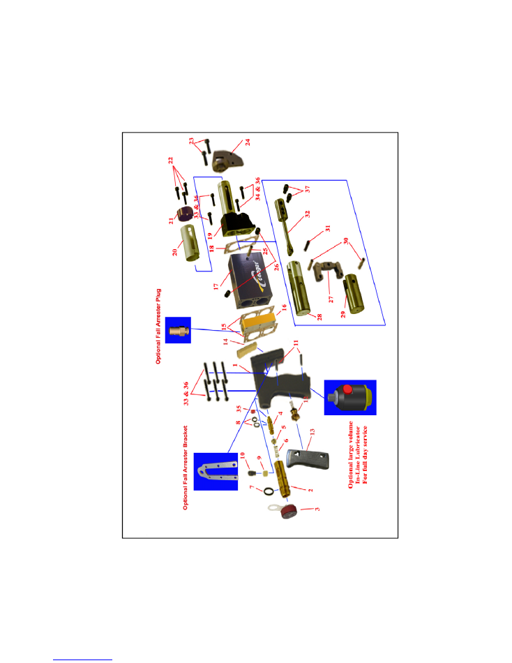
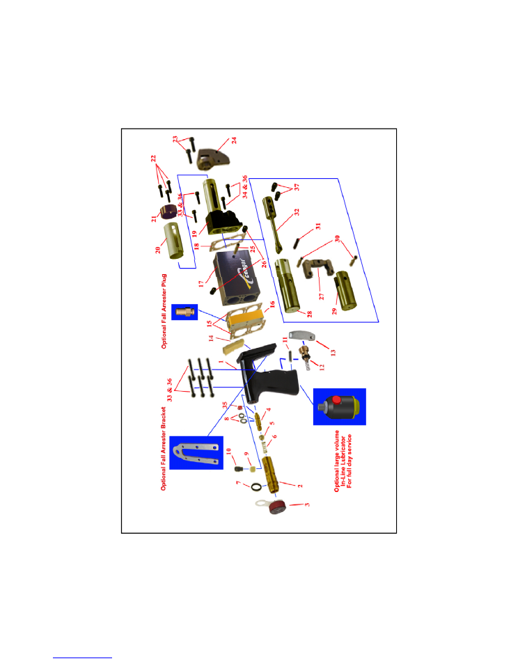
CL
50
&
75
Exploded
View

Item
Part
No.
Descrip
on
Number
Per Tool
Item
Part
No.
Descrip
on
Number
Per tool
1
95
50
Handle
1
19
11
43
Front
end
com
p
lete
1
2
95
54
Iso
la
tor
bo
dy
1
20
11
44
Silencer
Gu
ar
d
1
3
95
53
Oil
Cap
&
Re
tainer
1
21
11
43A
Front
End
Cap
1
4
95
55
Iso
la
tor
Nozzle
1
22
54
16
0
Front
cap
scre
ws
3
5
95
59
Oil
Control
Bal
l
1
23
54
16
0
Screws—Nose
p
iece
2
6
93
34A
Spring
1
24
50
45
/5
07
5
Nose
piece(
1/
2
”
‐
3/4
”)
1
7
95
61
‘O’
Ring
Large
2
25
11
47
Centre
Sh
a
1
8
95
60
‘O’
Ring
Small
2
26
55
51
6
Screws
fo
r
above
2
9
95
57
Détente
Spri
ng
1
27
11
50
Link
to
Pisto
n
s
1
10
95
56A
Lock
Screw
1
28
11
48
Top
Pi
sto
n
1
2
to
10
95
52
Iso
la
tor
A
sse
m
b
ly
29
11
52
Bo
om
Pi
sto
n
1
11
51
83
4
Roll
Pi
n
‐
Trigger
2
30
11
47
Pin
to
Link
2
12
50
03
4
Valve
in
Handle
1
31
11
47
Pin
to
Pede
sta
l
1
13
95
02
Trigger
1
32
11
53
‐
5
Pede
stal
1
14
95
06
Filter/Gauze
1
33
55
40
Screw
‐
Handle
/Fro
n
t
8
15
95
38
Gasket
2
34
55
20
Screw
‐
Fron
t
Lower
2
16
11
39
Valve
Un
it
1
35
95
60
&
95
61
Iso
la
tor
seals
1
17
11
41
L
Bo
dy
1
36
W55
Serrated
Washer
10
18
11
42
Gasket—
Front
end
1
37
50
68
Screw
‐
Blade
Grip
2
CL
50FT
&
75FT
Exploded
View

Item
Part
No.
Descrip
on
Number
Per Tool
Item
Part
No.
Descrip
on
Number
Per tool
1
95
50
FT
Handle
1
19
11
43
Front
end
com
p
lete
1
2
95
54
Iso
la
tor
bo
dy
1
20
11
44
Silencer
Gu
ar
d
1
3
95
53
Oil
Cap
&
Re
tainer
1
21
11
43A
Front
End
Cap
1
4
95
55
Iso
la
tor
Nozzle
1
22
54
16
0
Front
cap
scre
ws
3
5
95
59
Oil
Control
Bal
l
1
23
54
16
0
Screws—Nose
p
iece
2
6
93
34A
Spring
1
24
50
45
/5
07
5
Nose
piece(
1/
2
”
‐
3/4
”)
1
7
95
61
‘O’
Ring
Large
2
25
11
47
Centre
Sh
a
1
8
95
60
‘O’
Ring
Small
2
26
55
51
6
Screws
fo
r
above
2
9
95
57
Détente
Spri
ng
1
27
11
50
Link
to
Pisto
n
s
1
10
95
56A
Lock
Screw
1
28
11
48
Top
Pi
sto
n
1
2
to
10
95
52
Iso
la
tor
A
sse
m
b
ly
29
11
52
Bo
om
Pi
sto
n
1
11
51
83
4
Roll
Pi
n
‐
Trigger
1
30
11
47
Pin
to
Link
2
12
50
03
4
Valve
in
Handle
1
31
11
47
Pin
to
Pede
sta
l
1
13
95
02
FT
Trigger
1
32
11
53
‐
5
Pede
stal
1
14
95
06
Filter/Gauze
1
33
55
40
Screw
‐
Handle
/Fro
n
t
8
15
95
38
Gasket
2
34
55
20
Screw
‐
Fron
t
Lower
2
16
11
39
Valve
Un
it
1
35
95
60
&
95
61
Iso
la
tor
Seal
s
1
17
11
41
L
Bo
dy
1
36
W55
Serrated
Washer
10
18
11
42
Gasket—
Front
end
1
37
50
68
Screw
‐
Blade
Grip
2

IF THE SAW DOES NOT OPERATE
1
Check that the isolator is switched on.
2
Check air supply is correct.
3
Valve in handle (part no. 50034) could be worn and/or the seal is
broken, blocking an air passage. Check and replace if necessary.
4
Valve unit (Part No. 1139) may be stuck.
IT IS IMPERATIVE TO REMOVE
THE SAW FROM THE AIRLINE BEFORE COMMENCING THIS CHECK.
Remove the two hexagonal nuts, push out valve piston with a pencil,
keeping note which end is top. Clean with oil only, NEVER USE
ABRASIVE. Clean valve bore with oil, re
‐
fi
t piston from top, keeping the
seal at the top end. Tighten nuts and reconnect saw to air supply.
REPLACEMENT
OF
PISTONS
ON
1
The old pistons must be removed through the front of the body (blade
end) a er removing handle and front, push the top piston forward
(bo om piston rearward) this will bring the link shoulders clear of the
cylinder walls.
2
Remove the centre sha , by
fi
rstly removing the two retaining screws
(Part No. 55516) and pushing the sha out carefully.
3
Push the top piston forward, (the bo om piston will follow) un l
everything comes out.
4
Before re
fi
ng, ensure that each piston is a smooth sliding
fi
t in it’s
own bore, without being able to feel slackness.
5
Insert the pistons in to the bores from the front, in the same staggered
rela onship as during removal, to ensure that the link does not
damage the cylinder bores.
6
Re
fi
t the centre sha and securing screws, using a thread lock
adhesive on the screws.
7
Check that the pistons slide smoothly over the full travel, without
s cking.
8
REPLACEMENT
OF
ISOLATOR
ASSEMBLY
1
All the parts of the isolator are available separately, however
for ease of service, we o
ff
er an
isolator assembly (Part No 9552)
complete with retaining screw and détente spring, this has the
seat bonded in place already, and can be
fi
ed in seconds.
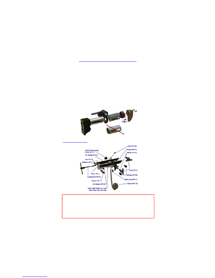
PIPE
CUTTING
WITH
THE
CL50
&
75
A clamp kit can be
fi
ed to the CL saws, (Part No CCSG3) allowing the
machine to mount on pipes and sec ons.
To
fi
t the parts required on the saw:
‐
1.
remove the nosepiece and silencer
2.
Fit the carrier over the front end tube, all the way to the back, and
clamp ght with the Allen key provided.
3.
Slide on the new shortened silencer, and re
fi
t the nosepiece.
The clamp carrier can remain on the saw for normal use when the clamp is
not in use.
Always
remove
the
saw
from
the
airline
before
commencing
any
maintenance
work.
Only
fi
t
genuine
Cengar
parts
and
accessories,
or
safety
may
be
compromised
Clamp
CP1
Spares

NEVER
1
NEVER
fi
t breakable “All
‐
Hard” blades in Cengar saws, these
can sha er causing injury to yourself and others.
2
NEVER
operate saw without wearing safety glasses
3
NEVER
operate saw whilst you, or others are near the saw
blade, which can cause serious injury or trapping
4
NEVER
use excessive force, this may increase vibra on
above safe levels
5
NEVER
hold the Cengar saw in a vice by the body, this will
distort the bores, rendering the tool inopera ve.
6
NEVER
screw nameplates to the body, as the screws may
penetrate an airway or bore.
7
NEVER
operate the Cengar saw without lubrica on.
8
NEVER
be tempted to clean internal parts with anything other
than a clean lint free cloth, and M.S. Cleaner, or Cengar Green
oil.
9
NEVER
modify Cengar saws or use non Cengar parts, this will
invalidate ATEX approval, and warranty.
ALWAYS
1
ALWAYS
use Cengar green oil for best results. Keeping the saw
clean and well oiled will give excellent reliability, and a long
life.
2
ALWAYS
use Cengar Bi
‐
Metal Sha erproof blades, for safety,
and best cu ng performance
3
ALWAYS
isolate the air supply when changing blades.
4
ALWAYS
wear eye protec on when using sawing machines.
5
ALWAYS
keep the nosepiece abu ed to the work to prevent
excessive vibra on
6
ALWAYS
isolate the machine when not in use
7
ALWAYS
keep others away from the saw blade to prevent
injury or trapping
8
ALWAYS
have machines vibra on tested annually to ensure
exposure is kept to the minimum
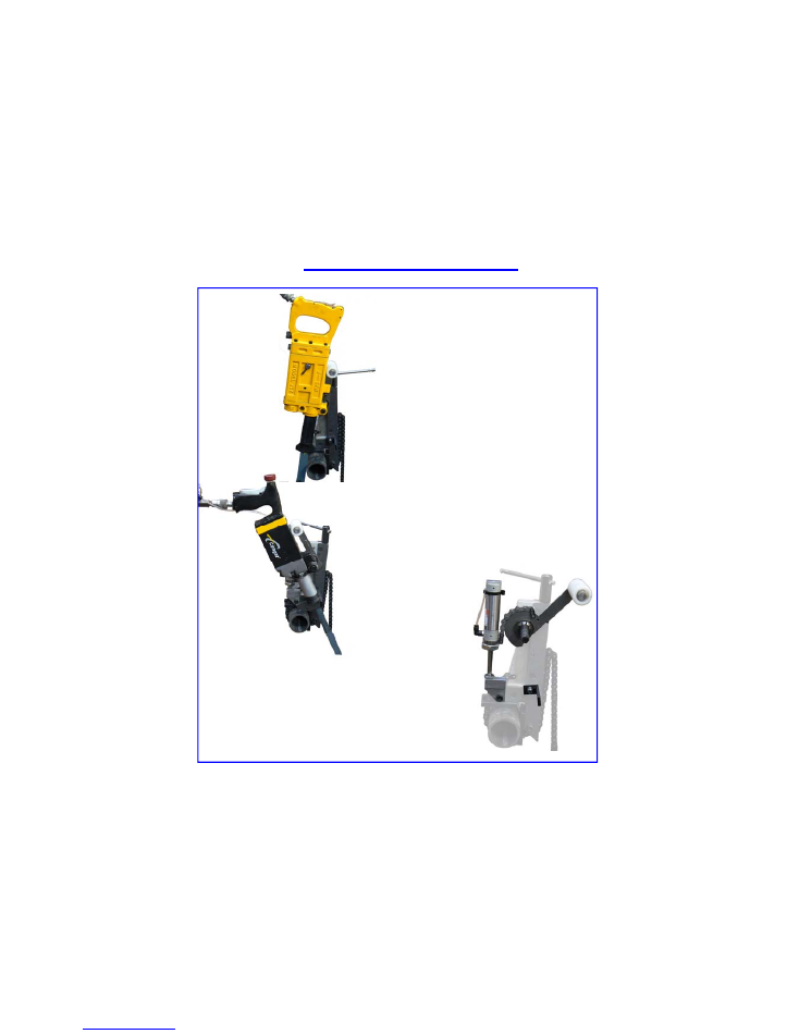
Power
Feed
Clamp
Kits
Allows Cengar CL75 and JSZ saws to be used
hands
‐
free, to accurately cut pipes and
sec ons up to the capacity of the machine.
The force applied is in
fi
nitely variable, and
can be altered during the cut to allow for
varying thicknesses of material.
“in
‐
situ” work can be done in ght spaces or
very narrow trenches due to the compact
actuator design
Hand arm vibra on
fi
gures are reduced to
Zero
Cuts are kept square ready for weld joints
Needs only 95mm of pipe length exposed
Gives faster cu ng and extends blade life
Operators are free to stand clear, or prepare
Complete power feed clamp
CP1P
As above plus CL75 mount kit
CCSG3P
Retro
fi
t kit for CP1 clamp.
CP1RK
Op onal
extras
9507CFA Op onal fall arrester plug to a ach to spring balance
1139FA Op onal Fall Arrester Bracket to a ach to spring balance
LUB01
Op onal In
‐
Line lubricator 28cc capacity, runs full day per
fi
ll
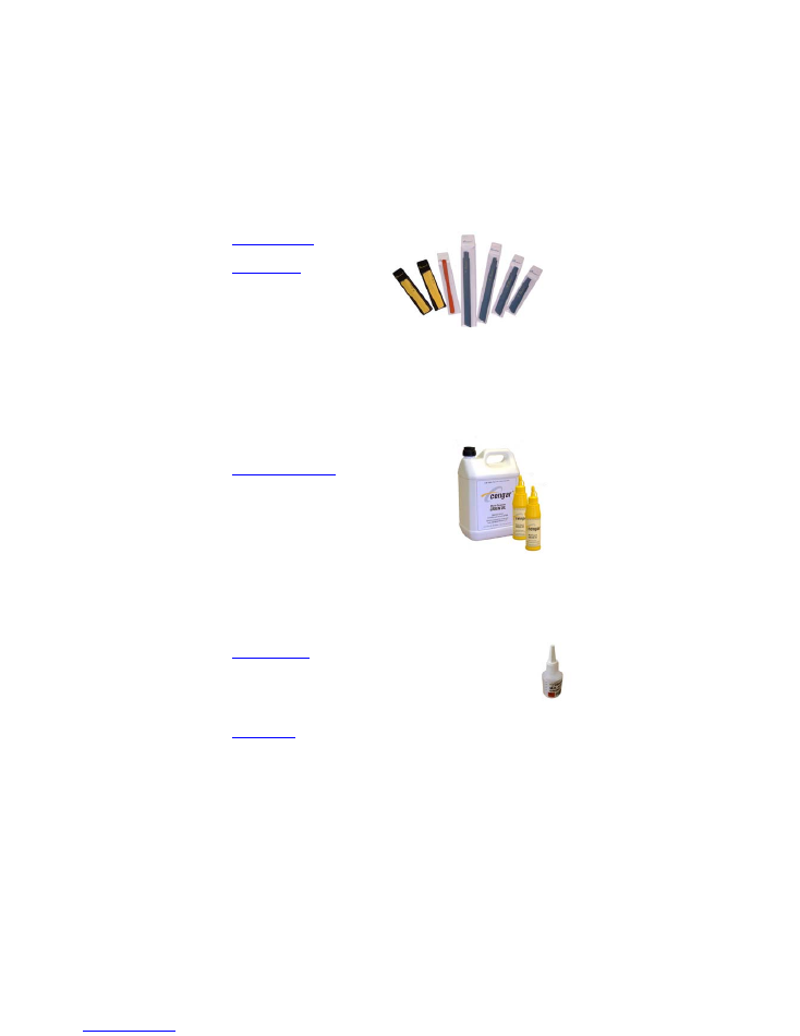
ACCESSORIES
Saw
Blades
MC 220/24
12 mm deep blade for general cu ng 24 TPI
MB 150/??
150 mm long x 19 mm blade, pitches 10, 18, or 24
MB 200/??
200 mm long x 19 mm blade, pitches 10, 18, or 24
MB 250/??
250 mm long x 19 mm blade, pitches 10, 18, or 24
MB 300/??
300 mm long x 19 mm blade, pitches 10, 18, or 24
Other sizes and types available on request
Cengar
Green
Oil
GO 9107P
Cengar Green Oil 250 ml plas c bo les for all air tools
GO 9109
As above in 5 litre container
GO 9110
As above in 25 litre container
M.S.
Cleaner
MS 9105
1 litre General purpose cleaning
fl
uid for air tools.
MS 9125
50 ml. In a dropper bo le.
‐
Enough for 10 tools
Always
use
plenty
of
Cengar
green
oil
a erwards.
Nosepiece
5045
Replacement nosepiece/blade guide for 12 mm deep blades
5075
Alterna ve nosepiece/blade guide for 19 mm deep blades

Cengar. Ltd.
Spring
fi
eld Works, Saddleworth Road
Halifax, England HX4 8LZ
Tel: 01422 377904 Fax: 01422 377161
enquiries@cengar.com
www.cengar.com
SERVICE
We o
ff
er a full factory repair and refurbishment service for
Cengar Saws,
‐
normally within 5 working days. Quota ons at
no charge can be given before work is carried out.
DISTRIBUTOR
ADDRESS
Original Instruc ons Document No. MAN5075ENG/01 Issue 09 (July ‘15)