Full Text Searchable PDF User Manual
(ES) Manual de instrucciones
(EN) Operating Instructions
(FR) Notice d’emploi
(DE) Bedienungsanleitung
(IT) Manuale di istruzioni
(PT) Manual de instruções
miawa
EN

Index
1.
Safety considerations ............................................................................................................................................3
2.
Features ..................................................................................................................................................................6
3.
Parts of the equipment ..........................................................................................................................................8
4.
Installation accessories ........................................................................................................................................9
5.
Especificaciones técnicas
.....................................................................................................................................9
6.
Main functions .................................................................................................................................................... 10
7.
Hydraulic diagram ............................................................................................................................................... 11
8.
Pilot lights and alarms ........................................................................................................................................ 12
9.
Installation ........................................................................................................................................................... 13
10
. Use of the equipment ....................................................................................................................................... 14
11
. Maintenance ..................................................................................................................................................... 15
12
. Steps for replacing the filters
........................................................................................................................... 16
13
. Troubleshooting ................................................................................................................................................ 17
EN
3
1. Safety considerations
Read and follow all the steps carefully before installing and using your equipment.
Failure to follow these sa-
fety precautions may pose a hazard.
Warnings:
if you do not heed the content of this section, this could cause perma-
nent damage to the MIAWA equipment or serious injury.
Notes:
if you do not heed the content of this section, this could cause damage to
certain parts of the MIAWA equipment or injury to others.
•
The equipment does not include a pressure regulator. Installing one is recommended if your mains pressure
is greater than 4 bars
.
•
Minimum inlet pressure of 2 bars is recommended for the model without pump.
•
If your inlet pressure is below 2 bars, the model with pump is recommended.
•
The model with pump requires minimum inlet pressure of 0.5 bars.
•
Before connecting the mains power, you must connect the water supply and make sure there are no leaks.
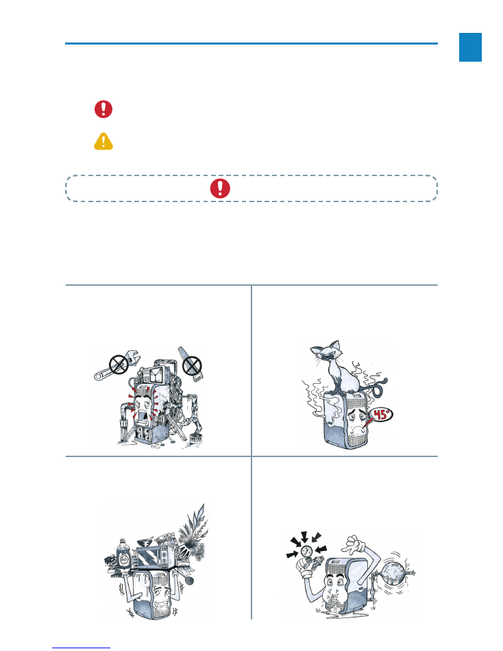
Warnings
Do not disassemble or modify this equipment yourself!
Manipulate the equipment solely to change consumables.
Unauthorised disassembly or modification of the equip
-
ment can lead to malfunction or water leaks in the machi-
ne. Contact the Technical Service of your nearest distribu-
tor in the event of malfunction.
Do not place foreign objects on top of the machine!
Blocking the dissipation of heat could cause damage to it.
Do not use under conditions of high pressure wi-
thout a pressure regulator!
Use under high water pressure conditions can cause
breakage of the system pipes, water leakage, malfunction
of the machine or serious damage. P>4bars.
Do not place heavy objects on top of the equipment!
If you place heavy objects on top of the equipment, this can
cause damage to its casing or interior which can lead to water
leakage, malfunction of the machine or even serious injury.
EN
4
Ultraviolet light
This equipment contains an ultraviolet lamp. The ultravio-
let light emitted may cause annoyance or damage to the
skin and eyes.
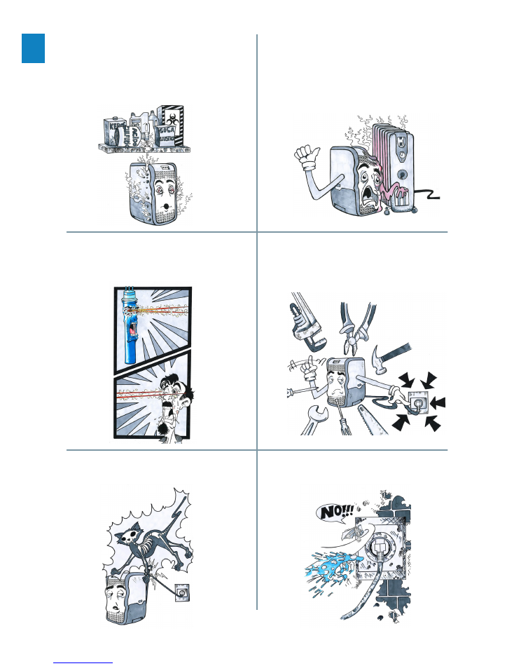
When you install or repair the machine, it must be
disconnected from the power supply!
Otherwise, you could suffer electric shock. Under no cir-
cumstances should the equipment be opened while con-
nected to the mains power.
Do not touch the plug with wet hands!
This can cause electric shock.
Do not damage the cable or the plug!
Doing so could cause electric shock, shortcircuits or a fire.
Do not let the equipment come into contact with co-
rrosive materials!
These materials can corrode the outer casing and affect
the interior parts. Certain toxic or hazardous compounds
could penetrate the water pipes, lead to contaminated wa-
ter and leaks, which could cause injury to yourself and/or
others.
Do not place the equipment near heat sources!
Do not place the equipment near a heat source or where
the temperature is excessively high as this could cause
warping damage or leaks, which could lead to injury to
yourself and/or others.
EN
5
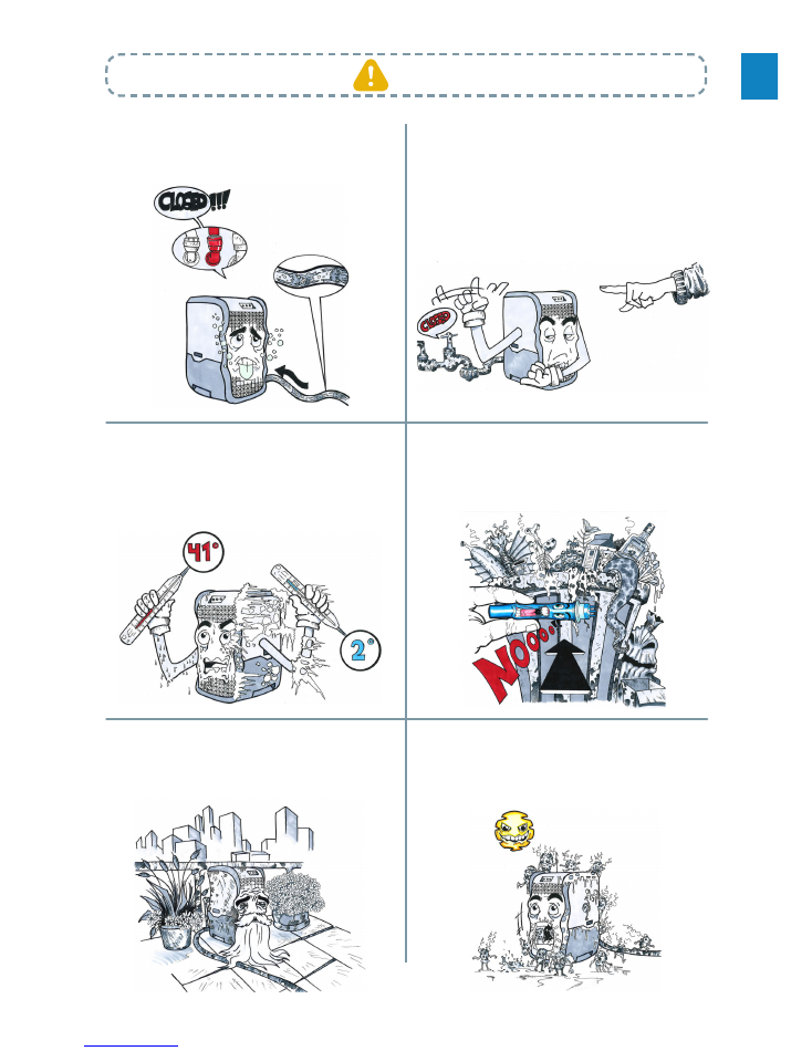
Notes
Do not use the equipment with a blocked drain!
If the equipment is used when the drain is blocked, this could
cause backflow of reject water into the equipment and conta
-
mination to enter.
The reject water drainage pipe should never be bloc-
ked!
When the reject water drainage pipe is blocked, this could
lead to high concentrations of TDS, clogging of the mem-
brane or malfunctioning of the MIAWA equipment.
Discard the lamp at the specific collection points for was
-
te containing mercury, and not with the normal domestic
waste. For more information, contact your local waste dis-
posal service.
The inlet temperature cannot exceed 38°C or be
lower than 5°C!
In the inlet temperature exceeds 38°C or is lower than 5°C,
this could damage the reverse osmosis membrane and
cause malfunctioning of the equipment.
Do not use this equipment outdoors!
If the equipment is used outdoors, there may be accelera-
ted ageing of equipment pipes and parts, which could cau-
se leakage or machine malfunction.
Do not use the equipment under direct sunlight!
If the equipment is placed in direct sunlight for a period, it could
become a breeding ground for microorganisms which would
reduce water quality as they can contaminate different parts
inside the machine.
EN
6
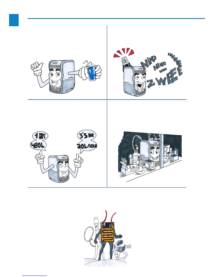
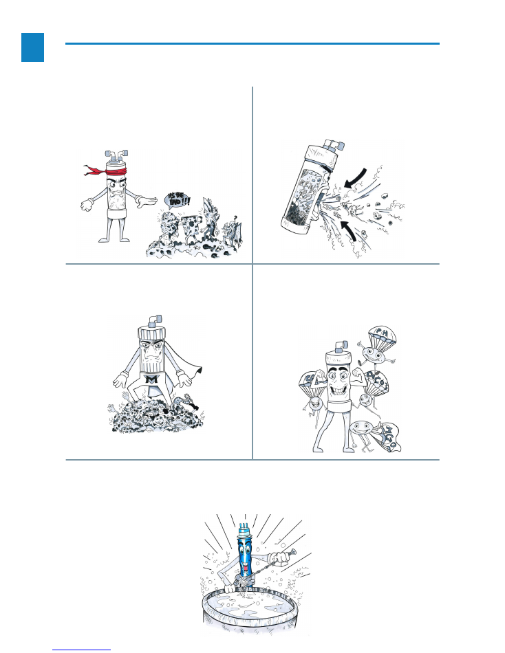
2. Features
1. Guaranteed water quality
Water of pH 7.4 and total optimal salinity monito-
red with a TOS reader are obtained as a result of
the full water treatment undertaken in the machine.
3. Equipment monitoring
The equipment has light and sound signals to in-
form the user of its status, letting them know whe-
ther any maintenance is necessary.
5. Safety elements
Tank level gauge to prevent overflow. Inlet pressure
switch to ensure proper working. Leak and moisture
sensor.
4. Ergonomic and compact design
Equipment of ideal size for beneath the sink, and
easy to open for maintenance and cleaning of all
the components.
2. Stable water flow
The equipment has a filter system capable of pro
-
ducing up to 480l/day at 3.5 bars (20l/hour), as
well as a 5 litre tank for immediate availability of
purified water.
EN
7
2. Features
6. Safe design
Made of high-quality materials; ABS plastic for the
outer casing and polypropylene for the tank and its
covers. Food-grade plastic free of BPA. Tropicalized
electronic circuitry (unaffected by damp, condensa-
tion or possible contact with water).
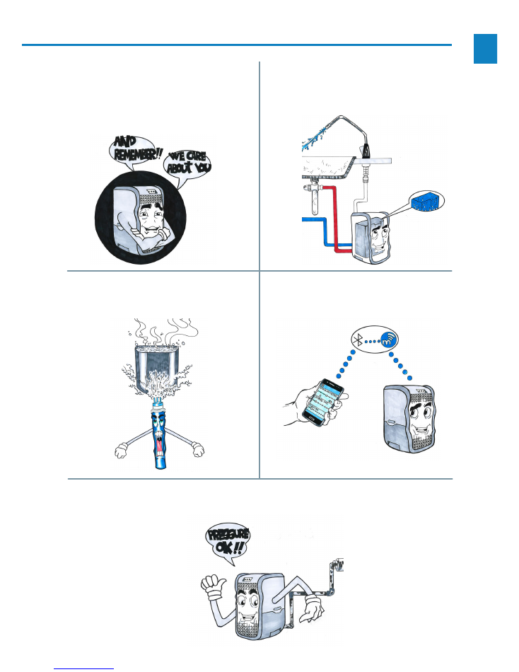
9. Bluetooth connection
You can connect via Bluetooth to check the equip-
ment status and settings.
8. Simple supply of water
The equipment automatically replenishes the water
in the tank, connecting and disconnecting the ele-
ments necessary, merely by opening the tap.
7. UV lamp
This is activated in sequence to sterilise the water
in the tank.
10. Working pressure
The equipment allows inlet working pressures of
0.5 to 6 bars.
EN
8
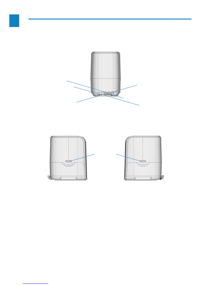
3. Parts of the equipment
Side clips for
opening
Programmer connection
Power supply
Tap connection
Water inlet (BLUE)
Permeate (water produced) (WHITE)
Reject, drain (RED)
EN
9
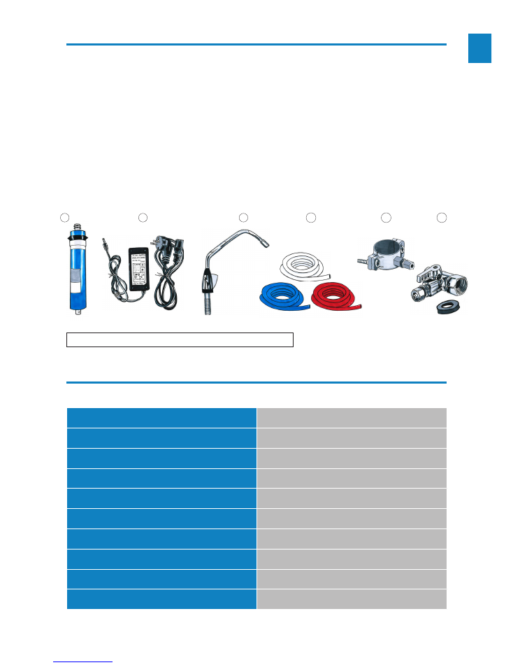
4. Installation accessories
1.
Quick installation guide.
2.
Sticky label of equipment light and sound signals.
3.
150GPD membrane.
4.
AC100-240V 50/60Hz power supply.
5.
Electronic tap.
6.
Installation kit:
6.
1 Vinyl pipes: 2m white pipe 3/8” / 2m blue pipe 1/4” / 2m red pipe 1/4”.
6.
2 Drain clamp.
6.
3 3-way 3/8” inlet valve.
5. Especificaciones técnicas
Supply
AC 220-110V 50/60Hz
Power consumption
55W
Mains water pressure
0,5 ~ 6 bars (if greater than 4 bars, use a regulator)
Working pressure model without pump
2 ~ 6 bars
Working pressure model with pump
0,5 ~ 4 bars
Inlet temperature
5 - 38ºC
Maximum TDS value of inlet water
≤1500PPM
Maximum daily water production
480 liters
Flushing method
Automatic
Type of protection against electric shock
Type II
Maximum cable length available for the electronic circuit is 2.5 m
3
4
5
6.1
6.2
6.3
EN
10
6. Main functions
The MIAWA water filtering process consists of:
5.
The fifth stage is ultraviolet hygienisation
:
This renders the water hygienic using ultravio-
let light. It does not add any chemicals, odour or
taste to the treated water.
4.
The fourth stage is a re-mineralisation post-filter
:
This furnishes the right amount of minerals to
the outlet water, yielding a non-corrosive water
with ideal organoleptic properties. It adjusts the
pH of the permeate and regulates the levels of
calcium and magnesium.
2.
The second stage is an encapsulated GAC filter:
It can effectively absorb chlorine, disinfectant sub-
products, odours, colours and other substances.
3.
The third stage is the 150 GPD RO membrane:
This can effectively eliminate bacteria, viruses,
heavy metals, pesticide wastes and other harm-
ful substances in the water.
1.
The first stage is an encapsulated 5-micron se
-
diment filter:
It can effectively filter out rust, sand, other larger
particles and solid impurities in the water.
EN
11
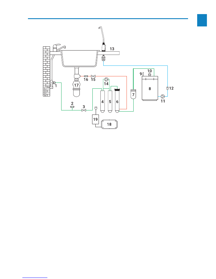
7. Hydraulic diagram
1.
Untreated mains water valve.
2.
Inlet electrovalve 2/2 24V DC with woven stainless steel filter.
3.
Low pressure switch to detect leaks.
4.
5 micron sediment filter.
5.
Activated carbon filter.
6.
Membrane-holder with 150GPD membrane.
7.
Re-mineralisation post-filter.
8.
Unpressurised tank with useful capacity of 5 litres.
9.
Water level gauge with three states: Minimum, Maximum and Overflow.
10
. 14 W ultraviolet lamp.
11
. Permeate pump 24VDC.
12
. Conductivity meter (TDS).
13
. Treated water dispenser tap.
15
. Flushing electrovalve.
16
. Anti-return valve for water.
17
. Drain of domestic sink.
18
. Main electronic circuit of the equipment.
19
. Input power AC100-240V 50/60Hz and output DC24V 4A.
* 14.
Inlet booster pump. Optional element for dwellings with low mains water pressure. Should this be insta-
lled, the hydraulic order would be: Sediment (
4)
, Booster pump (
14
), Activated carbon (
5
), Membrane-holder (
6
)
and Post-filter (
7
). Electrical component.
EN
12
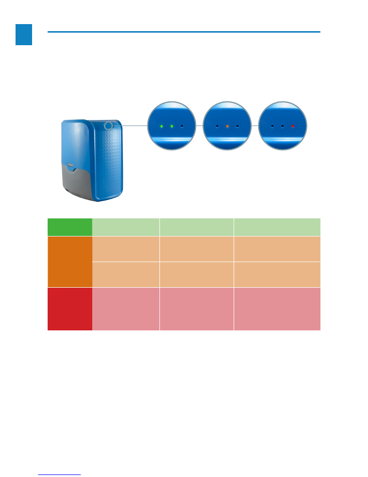
8. Pilot lights and alarms
This equipment has a monitoring system using acoustic signals which are accompanied by the pilot lights on
the equipment itself, and these signals indicate the following:
GR
EEN
-
-
The equipment has power and there is no
anormaly.
AM
BER
LED flashing.
Triple acustic signal for 1 minute,
with 10 second gap, and repeated
every 30 minutes.
This indicates that the filters should be chan
-
ged because of their age or as a warning of
high TDS level.
LED steady.
Continuous acoustic signal.
Indicates that the tank is empty when the tap
is operated and the level gauge is at level 1.
RE
D
LED steady.
Uninterrupted continuous acoustic sig-
nal.
Indicates that the equipment is in a state of
alert due to:
a) Overflow or flooding.
b) Alarm due to component failure.
c) Electrical fault.
GR
EEN
AM
BER
RE
D
EN
13
The cabling used for the electronic circuit must be supplied by the
manufacturer. Under no circumstances may extensions be used.
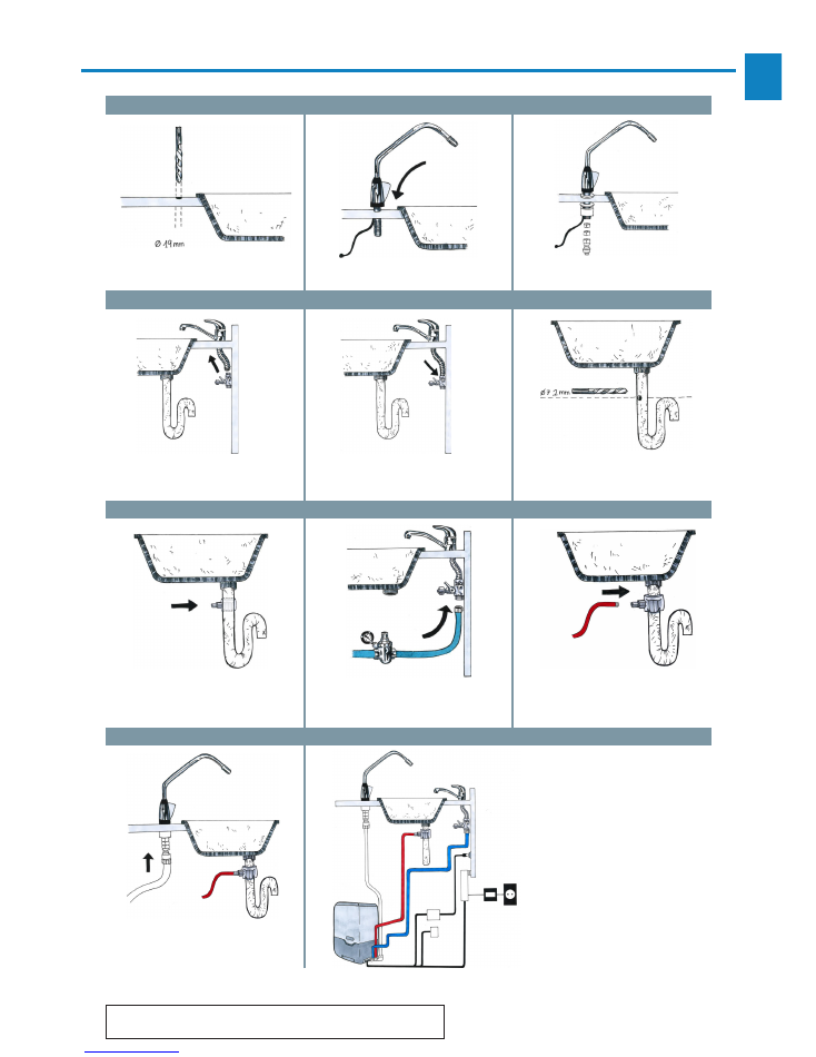
9. Installation
STEP 10
STEP 11
Connect the equipment outlet to
the auxiliary tap, and the other
end to the MIAWA outlet (white/
neutral pipe).
Effect the electrical connec-
tions to the equipment and
then connect to the mains
power. The auxiliary pump is
used when the inlet pressure
is insufficient.
1 - 24V transformer
2 - MIAWA programmer
3 - Optional auxiliary pump
STEP 1
STEP 2
STEP 3
Drill a hole in the sink top using a
19mm bit.
Pass the tap through this hole.
Install the tap as shown in the
figure, in the same order.
STEP 4
STEP 5
STEP 6
Disconnect the mains cold water.
Install the 3 way valve into the
mains cold water supply.
Make a hole in the sink drain
using a 7.2mm bit.
Prepare this hole for the
equipment drain.
Connect the 3-way valve inlet to the
MIAWA connector (blue pipe) using
the pressure reducer.
Connect the equipment drain (red
pipe) to the sink drain.
STEP 7
STEP 8
STEP 9
EN
14
10. Use of the equipment
Preparation prior to use
- Install the equipment as set out in the previous point.
- Connect the equipment; plug the transformer intake to the mains socket of the installation.
- Open the water valve and ensure that the equipment starts to produce osmotised water.
From this moment, MIAWA will supply with water of guaranteed quality.
Conditions of use
•
This equipment requires an appropriate supply of water. Should the installation set up not meet certain
minimum standards this could cause malfunctioning.
• Miawa is fitted with an automatic washing system (flushing), programmed to work for 1.5 minutes every 6
hours. (The user can modify this parameter using the app)*
• The UV light comes on for 1 minute every 6 hours. (The user can modify this parameter using the app)*
*Only user number 3 (distributor)
Use of the equipment
The tap on the equipment itself activates the internal mechanisms when opened to provide the user with the
water filtered up to that moment.
The internal functioning of the equipment is:
a
. Through the inlet electrovalve, the mains water enters the equipment. This is activated when the tank level
gauge is at minimum or when we actuate the tap.
b
. The water enters the filter assembly: sediment; booster pump (if this is installed), activated carbon and
osmosis membrane.
c
. The waste water from the membrane is sent to the drain.
d
. The permeate water from the membrane passes through a re-mineralisation post-filter for subsequent sto
-
rage in the tank.
e
. The user, by means of the tap, opens the outlet valve, activating the permeate pump to extract the accumulated
water. As it leaves, the conductivity is measured to give a reading of the water quality.
For reasons of hygiene, the osmosis membrane contains chemical preservatives. This means that
the first water produced cannot be used, and therefore it
is very important to empty the first two
tankfuls
, by operating the tap until the pump stops (for each emptying operation).
EN
15
11. Maintenance
The MIAWA reverse osmosis equipment requires little maintenance:
Components such as the sediment pre-filter, activated carbon filter, reverse osmosis membrane and the re-mi
-
neralisation post-filter are subject to wear and have a limited duration. Their lifespans depend on local circum
-
stances, as the water of each region has its own composition. As guidance, we now show the duration of the
cited components:
• Sediment pre-filter: 12 months (depending on inlet water)
• Activated carbon filter: 12 months (depending on inlet water)
• Reverse osmosis membrane: 3-5 years (depending on inlet water)
• Re-mineralisation post-filter: 2 years
• UV lamp: 7000 hours
The duration of the elements shown is determined by certain parameters under laboratory conditions. Excessi-
ve variation in these parameters could shorten the lifespan of these components, as could the use of non-ori-
ginal spare parts and consumables.
To guarantee hygiene, the equipment needs to be sanitised on a regular basis, which involves cleaning the
elements that make up the filtering system.
Attention:
even when the valve is closed, the filter container vessels still contain a significant
amount of water. Have a container to hand when emptying to avoid water spillage.
Note:
if you replace the pre-filter or the post-filter, it is not imperative to replace the rest. If you replace
the reverse osmosis membrane, then the sediment pre-filter, the activated carbon filter, and the re-mate
-
rialisation post-filter should also be replaced.
EN
16
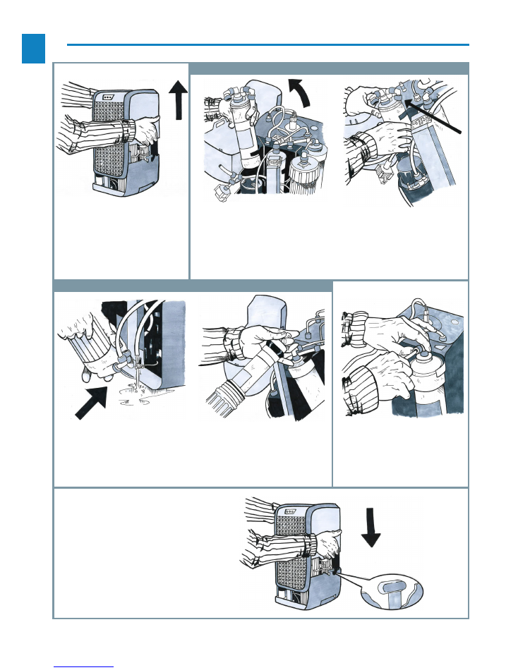
12. Steps for replacing the filters
A. REPLACEMENT OF SEDIMENT, ACTIVATED CARBON FILTERS AND RE-MINERALISATION POST FILTER
B. SUSTITUTION OF MEMBRANES
1. OPEN THE EQUIPMENT:
open
the lid of the equipment by pressing
the side clips. On raising the lid, be
careful with the LED panel and in
the event that this comes off, put it
back in its position on the front of
the base.
2.ADISCONNECTION OF FILTERS:
disconnect the pipes of the fil
-
ter to be changed by pressing the
quick-released clip, and undo all the
connections between the filter and
the valve.
2.B SUBSTITUTION OF FILTERS
CARTRIDGES:
effect all the connec-
tions between the new filter and the
valve just as they were.
5. CLOSING:
replace the lid and secu-
re it with the side clips, verifying that
the LED panel is properly in place.
3.A DISCONNECTION MEMBRA-
NE-HOLDER:
disconnect the pipes
of the membrane-holder by pressing
the quick-release clip and opening
the membrane-holder with its key.
3.B SUBSTITUTION OF MEMBRA-
NES:
substitute the new membrane
by placing it in the same position
and close the membrane-holder.
4:
put the new filter or membra
-
ne-holder back in the original posi-
tion and connect the pipes, making
sure they are held in place by the
quick-release clip.

EN
17
13. Troubleshooting
The following table shows the most common problems and how to resolve them:
ANOMALY
SOURCE
SOLUTION
It makes noise
A)
Defective outlet pump
B)
Inlet valve partially blocked
A)
Contact the authorised technical service
It works continually
A)
Lack of water
B)
Inlet valve closed
C)
Membrane saturated
A)
Check the general water inlet valve
B)
Contact the authorised technical service
C)
Change the membrane (authorised te-
chnical service)
The equipment has hal-
ted
A)
Power cable not plugged in
B)
Defective control circuit
A)
Connect the mains power
B)
Contact the authorised technical service
It loses water
A)
It has overflowed
B)
Defective o-ring
A)
Check the movement of the float
B)
Check the outlet pump closure gasket
C)
Check the connection of the internal
pipes Contact the authorised technical
service
No water comes out of
the tap
A)
The tank is empty
B)
The sediment filter is clogged
C)
The water circuit is blocked
D)
Outlet pump disconnected or de-
fective
E)
Reverse osmosis membrane clog-
ged
F)
Water inlet closed
G)
Lack of mains pressure
A)
Check the mains pressure
B)
Contact the authorised technical service
Unsuitable flavour
A)
Water stored for too long
B)
Tank dirty
C)
Filters used for too long
A)
Empty the circuit and clean the tank,
pipes and taps
B)
Clean the tank
C)
Change the filters
D)
Change the reverse osmosis membra-
ne. Contact the authorised technical
service.

EN
18
... Pending new information with possible modifications...