Full Text Searchable PDF User Manual
Version:1.0
PRO 200
2
0
1
7
.1
2
.2
7
User
Manual
Zero
Latency
Model: 7051(Transmitter)
3051(Receiver)
Foreword
-
Please read this manual carefully before you use this product and retain it properly
for future reference.
Features
Brief Introduction
02
02
03
04
05
09
13
15
18
05
07
09
11
Contents
About
this
manual
Packing list
Brief introduction
Specification
Wireless
HD
Transmitter
:7051
Wireless
HD
Receiver
:3051
Wireless
HD
Transmitter
:7051
Wireless
HD
Receiver
:3051
Trouble shooting
Mechanical information
- CVW reserves the authority to modify the instruction manuals.
- If there is any question or difficulty about the operation of product, please feel free
to contact us or the dealer.
As the widely use of live broadcasting , many problems about wiring appear, such as
the high cost and short life time of the cable. Further, some other factors affect the
user experience of live broadcast, such as the insufficient cable protection and the
tread bycrowded people, which will lead to the poor cable transmission capability or
even to accident. PRO200 provides you more convenient and safer solution for live
broadcasting. With the advantage of long distance transmission, plug-and-play usage,
it can satisfy your various indoor and out door shooting requirements. With addition of
its free cable wiring needed,it will bring much safer and more professional experience
to you!
02
Features
The product with its transmission distance of up to 200 meters can meet the demands
of film shooting, television broadcasting, live events, large conference, etc.
The product delivers uncompressed real-time 1080P/60Hz full HD video (4:2:2, 10bit).
Support HDMI, HD-SDI, 3G-SDI.
Full hardware design, plug & play;
Support manual setting for channel switching and broadcast mode.
Support SDI time code transmission (time code format: ATC_VITC, ATC_LTC).
Support SDI camera recording trigger function (Start/Stop Flag) transmission.
Comply with EDID Structure 1.1 and support HDMI 1.3.
Support AES128/256 bit image encryption.
LED Digits Display description
Product Installation
Transmission Distance Description
04
2
-
Pin
Lemo
to
BTap
SDI Cable
*1
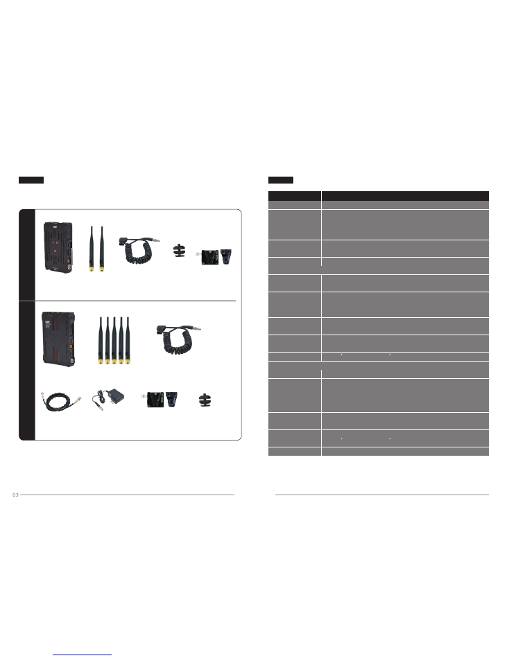
Packing List
Please check the package inside to assure it contains the parts as below,
if any parts missed, please contact the distributor or us.
Transmitter * 1
Antenna * 2
T
ra
n
s
m
it
te
r
Power Cable * 1
Hot-shoe
Stand * 1
V-Mount * 1
*Optional
2
-
Pin
Lemo
to
BTap
Receiver * 1
Antenna * 5
Hot-shoe
Stand * 1
Power Cable * 1
V-Mount * 1
*Optional
DC Adapter * 1
12V 2A Lemo 2 pin
*Optional
R
e
c
e
iv
e
r
* Some of the accessories are optional with extra cost, if you need to purchase,
please contact the distributor or us.
* If some changes on the appearance,logo and accessories, subject to the actual
received product.
Frequency
1080P 23.98/24/25/30/50/60
1080psf 23.98/24/25
1080i 50/59.94/60
720P 50/59.94/60
576P 576i 480p 480i
40MHz
PCM
ATC_VITC
ATC_LTC
Up to 200m
Transmitter
Antenna
External antenna * 2
Working Voltage
DC 7
V
~
36
V
7W
Temperature
Receiver
Working Voltage
Power Consumption
5
~
6W
Image
transmission
:
LED Digits Display
V-mount, 1/4" fixing screw hole
-
10
~
50
C
(
Working
);-
40
~
80
C
(
Storage
)
Item
Specification
Bandwidth
Video Formats
Audio Formats
Time Code
Transmission
distance
HDMI input,SDI input, Mini-USB,Lemo(0B/2pin) DC in,
Antenna RPSMA, Power switch
Mechanical Interface
Power Consumption
Antenna
External antenna *5
Receiver Sensitivity
-70dBm
HDMI output, SDI output, Mini-USB,Lemo(0B/2pin) DC in,
Antenna RPSMA,Power switch
Mechanical Interface
V-mount, 1/4" fixing screw hole
Temperature
-
10
~
50
C
(
Working
);-
40
~
80
C
(
Storage
)
Interface
Interface
* As the product's continous improvment, the performance, design and specifications
are subject to minus change without prior notice.
Specification
LED Digits Display
Display the working channel
Display the working channel
DC 7
V
~
36
V
5.15~5.25GHz(for FCC) and 5.725~5.85GHz (for FCC&IC)
.
.
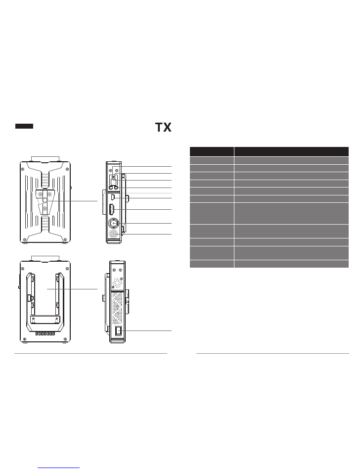
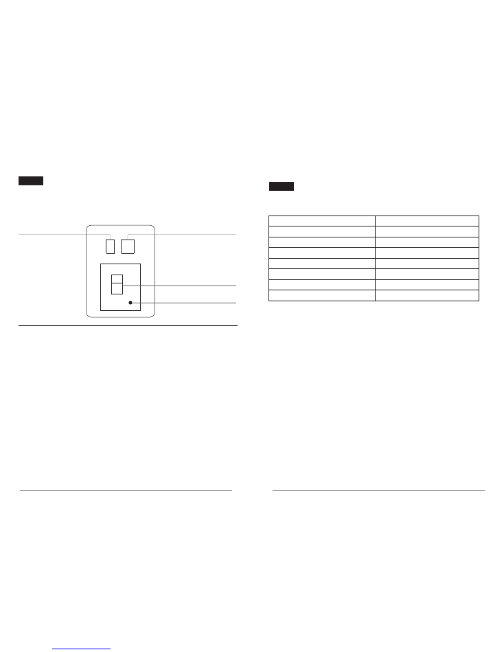
Transmitter Interface
LED Digits Display
OK Button
Confirm the function selection
CH Button
Switch the working channel
HDMI IN
HDMI IN
SDI IN
SDI IN
DC-IN
Power input interface (LEMO): support 7V to 36V
5.8G Antenna
Connector
Power Switch
Power ON/OFF
V
-
MOUNT
V
-
MOUNT
Sony F-Type
Battery Plate
Power Switch
Display the working channel
Mini USB
Be used for software upgrading
Sony F-Type
Battery Plate
06
05
Mechanical Information
Model
:
7051
5.8G Antenna
Interface
Power indicator
Video indicator
OK Button
CH Button
Mini USB
HDMI IN
SDI IN
DC-IN
Transmitter Interface Description
Item
Specification
(
Notice: please confirm the polarity before you
plugging in the power supply.)
Connect with RP-SMA antenna
Support installation of V-mount devices
Be used for installing external Sony F-type battery
LED Digits Display
5.8G Antenna
Interface
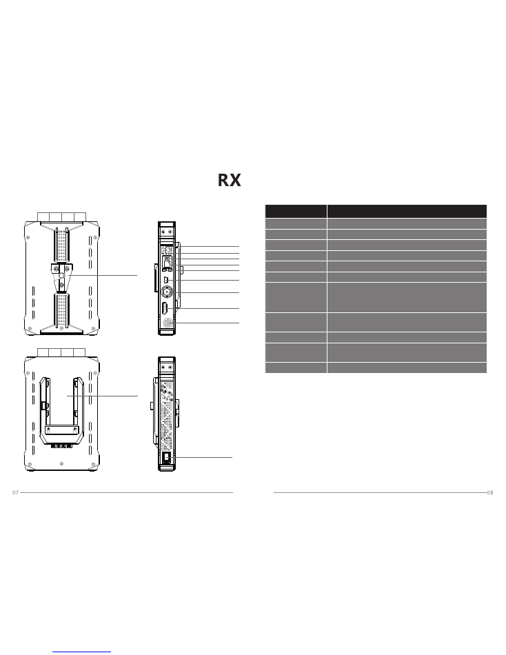
Receiver Interface
Model
:
3051
5.8G Antenna
Interface
Power indicator
Video indicator
Mini USB
LED Digits Display
OK Button
CH Button
SDI Out
HDMI Out
DC-IN
V-MOUNT
5.8G Antenna
Interface
Sony F-Type
Battery Plate
Power Switch
LED Digits Display
OK Button
Confirm the function selection
CH Button
Switch the working channel
HDMI OUT
HDMI OUT
SDI OUT
SDI OUT
DC-IN
Power input interface (LEMO): support 7V to 36V
5.8G Antenna
Connector
Power Switch
Power ON/OFF
V
-
MOUNT
Display the working channel
Mini USB
Be used for software upgrading
Sony F-Type
Battery Plate
Receiver
Interface Description
Item
Specification
(
Notice: please confirm the polarity before you
plugging in the power supply.)
Connect with RP-SMA antenna
Support installation of V-mount devices
Be used for installing external Sony F-type battery
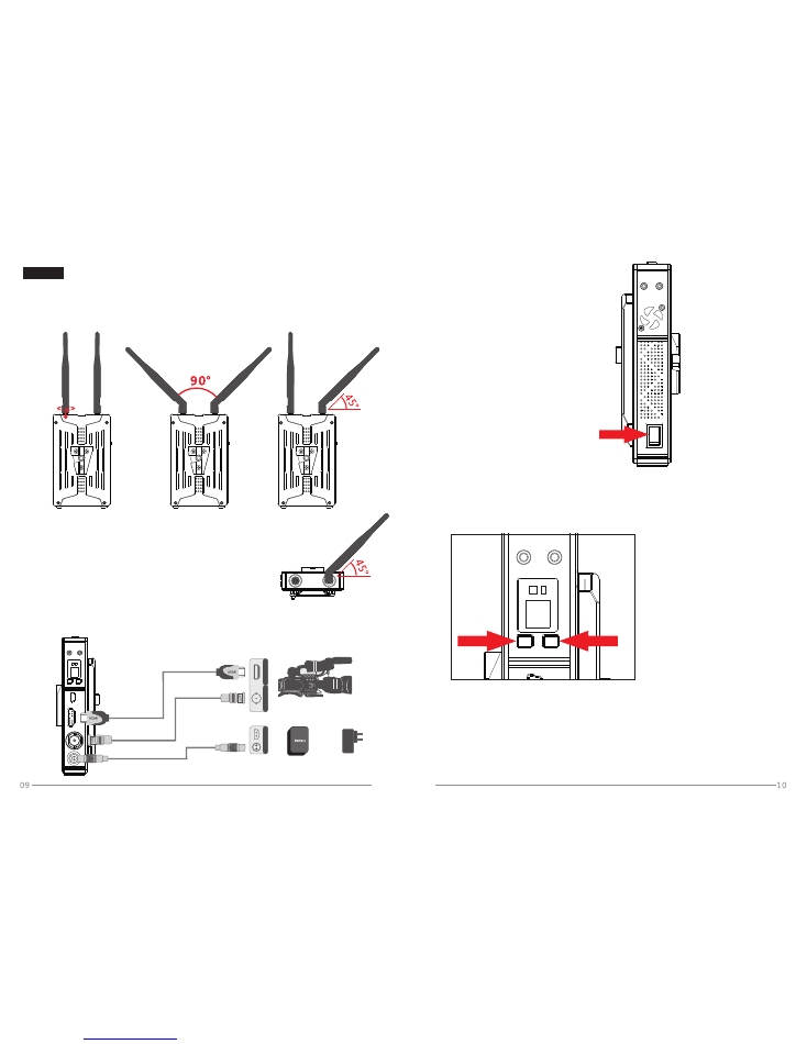
1. Fix the antennas and adjust their angles as shown in the figure below.
(For details, see the Transmission Distance Description.)
TX
H
D
M
I
S
D
I
D
C
DC IN
SDI IN
H
DMI IN
7V-36V
Product Installation
Transmitter Installation Steps:
Notice: please rotate the golden
mental part of antenna to
fasten the antenna.
Antenna Pattern 1:
90° angle in the same plane
Antenna Pattern 2:
Right side 45° angle
rotation towards backside
2. Connect Tx with the camera via corresponding
power cable and HD video cables as shown in the figure below.
3. Turn on the power switch to start
power supplying.
Power Switch: ON turn on
OFF turn off
4. Press “CH” button to select the corresponding working channel of
receiver and then press “OK” button for confirmation.The LED digits
display will display one of the characters from 1 ~ 9, A and b when the
video signal of device is normal.
5. The transmitter supports manually switching the SDI audio input mode by
long pressing “OK” button. (Notice: This function is only valid for SDI
audio input and won’t affect the HDMI audio input.)The default value of
SDI audio input mode is 0 and the decimal point will be set to be non-bright
under this mode; long press “OK” key button for more than 3 seconds,
and then the LED digits display will display SDI audio input mode as 1 while
the decimal point will be bright.
Li-battery
12V power adapter
Camera
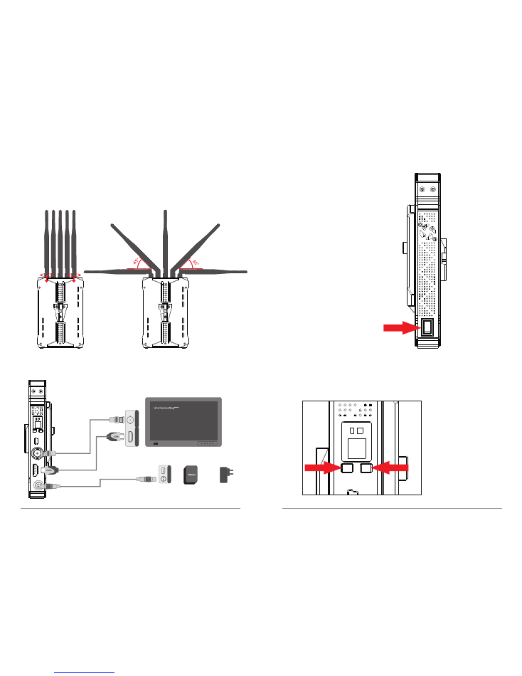
RX
11
12
D
C
DC IN
7V-36V
H
D
M
I
S
D
I
SDI monitor
SDI OUT
HDMI OUT
Receiver Installation Steps:
1. Fix the antennas and adjust their angles as shown in the figure below.
Notice:
please rotate the
golden mental
part of antenna to
fasten the antenna.
2. Connect RX with the monitor via corresponding power cable and HD
video cables as shown in the figure below.
12V power adapter
Li-battery
3. Turn on the power switch to start
power supplying.
Power Switch: ON turn on
OFF turn off
4. Press “CH” button to select the corresponding working channel of
receiver and then press “OK” button for confirmation.The LED digits
display will display one of the characters from 1 ~ 9, A and b when the
video signal of device is normal; the monitor will display the image from
camera simultaneously.
13
14
LED Digits Display
Transmitter
Power Indicator
Video Indicator
SDI Audio Input Mode
LED Digits Display description
LED Digits Display Status
LED Digits Display
: Channel 1 ~ 4
Video Indicator
: Red: HDMI input; Yellow: SDI input
Power Indicator
: Illuminate in working mode
SDI Audio Input Mode:
Decimal point light is off: SDI Audio Input Mode 0
Decimal point light is on: SDI Audio Input Mode 1
Receiver
LED Digits Display
: Channel 1 ~ 4
Video Indicator
: Red: HDMI input;
Yellow: SDI input(Default: HDMI and SDI outputs are
both enabled by default.)
Power Indicator
: Flash slowly when the network is not connected.
Light on normally when the network is connected.
25PFS in = 25PFS out
29.97PSF=29.97PSF out
30PSF in = 30PSF out
23.98P in=23.98P out
24P in=24P out
25P in=25P out
29.97P in=29.97P out
30P in=30P out
50i in = 50i out
59.94i in = 59.94i out
60i in = 60i out
Support Full PSF resolution
Support Full PSF resolution
15
16
Provided that the product is working under the condition of line of sight
distance by adopting the optimal installation:
TX
:
7051
RX
:
3051
TX
:
7051
RX
:
3051
Transmission Distance Description
Transmission Distance
1. Make sure that the fixed angle between transmitter antennas is 90° in the same plane,
and enable the face-to-face transmission between transmitter and receiver.
Under such condition, the transmission distance is up to 300 meters.
2. Rotate the right side of the 2 transmitter antennas towards backside by 45°
as refer to the Antenna Pattern 2 as mentioned above. Under such condition,
the transmission distance is around 200 meters when the transmitter is revolving
during the shooting process.
3. If you require the transmission distance over 300 meters, please adopt the plate
antennas which are available from us for transmitter. Under such condition,
the transmission distance is over 1000 meters.
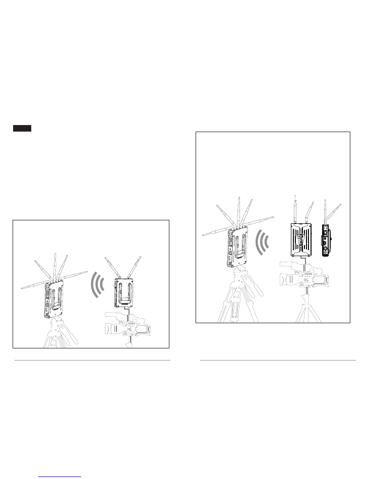
Optimal Distance
Make receiver to stand vertically; adjust antennas to a fan-shaped arrangement;
Make transmitter to stand vertically; adjust antennas to 90° angle in the same plane;
The distance of face-to-face transmission between TX and RX will
be up to 300 meters (line of sight).
Standard Distance
Make receiver to stand vertically; adjust antennas to a fan-shaped arrangement;
Make transmitter to stand vertically; adjust the right side of the 2 transmitter
antennas towards backside by 45°;
The distance of non-face-to-face transmission between TX and RX will be up to
200 meters (line of sight).
Antenna Pattern 2:
Right side 45° angle
rotation towards backside
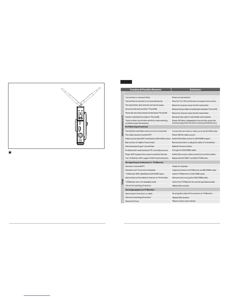
17
18
When the front side of the transmitter is not able
to face to the receiver, please try to adjust the
direction of transmitter antennas to make sure
that the formative fan-shaped arrangement
can face to the receiver for best signal transmission.
As shown in the right figure:
Notice: the channel 1 is not recommended in the long distance
transmission due to its limited performance.
Trouble shooting
Display“Link Connecting”
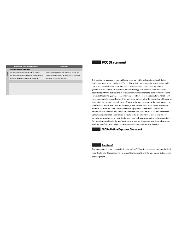
20
Image displayed,No audio
A
u
d
io
Video source mute
Volume too low
Audio format not supported
Something wrong with transmitter/ receiver
Turn on the audio of video source
Turn up the audio of video source
Switch the format of video source output
Restart the transmission kit
*
For more questions, please contact the distributor or us.
19
This equipment complies with FCC radiation exposure limits set forth for an uncontrolled environment.
This transmitter must not be co-located or operating in conjunction with any other antenna or transmitter.
This equipment should be installed and operated with minimum distance 20cm between the radiator &
you body.
This equipment complies Part 15 of the FCC Rules. Operation is subject to following two conditions:
1) This device may not cause hardful interference,and
2)This device must accept any interference receiced, including interference that may cause undesired
operation.

RSS
warning
This
device
complies
with
ISEDC
licence
‐
exempt
RSS
standard
(s).
Operation
is
subject
to
the
following
two
conditions:
(1)
this
device
may
not
cause
interference,
and
(2)
this
device
must
accept
any
interference,including
interference
that
may
cause
undesired
operation
of
the
device.
Le
présent
areil
est
conforme
aux
CNR
d'ISEDC
licables
aux
areils
radio
exempts
de
licence.
L'exploitation
est
autorisée
aux
deux
conditions
suivantes:
(1)
l'areil
ne
doit
pas
produire
de
brouillage,
et
(2)
l'utilisateur
de
l'appareil
doit
accepter
tout
brouillage
radioélectrique
subi,
même
si
le
brouillage
est
susceptible
d'en
compromettre
le
fonctionnement.
ISEDC
Radiation
Exposure
Statement:
This
equipment
complies
with
ISEDC
RF
radiation
exposure
limits
set
forth
for
an
uncontrolled
environment.
This
transmitter
must
not
be
co
‐
located
or
operating
in
conjunction
with
any
other
antenna
or
transmitter.
This
equipment
should
be
installed
and
operated
with
minimum
distance
20cm
between
the
radiator&
your
body.
Cet
appareil
est
Conforme
aux
limitesd'exposition
de
rayonnement
RF
ISEDC
établiespour
un
environnement
non
contrôlé.
Cetémetteur
ne
doit
pas
être
co
‐
implanté
oufonctionner
en
conjonction
avec
toute
autreantenne
ou
transmetteur.
Cet
équipement
doit
être
installé
et
utiliséavec
une
distance
minimale
de
20cm
entre
leradiateur
&
votre
corps.