Full Text Searchable PDF User Manual

Bosch Diagnostics
|
1 6 8 9 9 7 9 9 8 7
2 0 0 6 -0 9 -2 9
14 | KTS 530 / KTS 540 / KTS 570 | Contents
1.
O p er a tor instr u c tions
15
1.1
Im p o r ta n t n o te s
15
1.2
S a fe ty in s tr u c tio n s
15
1.3
E le c tro m a g n e tic c o m p a tib ility ( E M C )
15
1.4
D is p o s a l
15
1.5
B lu e to o th lim ita tio n s
15
1.6
Im p o r ta n t in fo r m a tio n re g a rd in g B lu e to o th
15
2.
D esc r ip tion of u nit
16
2.1
A p p lic a tio n
16
2.2
R e q u ire m e n ts
16
2.2.1 H a rd w a re
16
2.2.2 O p e r a tin g s y s te m
16
2.2.3 S o ftw a re
16
2.3
D e liv e r y s p e c ifi c a tio n
17
2.4
S p e c ia l a c c e s s o r ie s
17
2.5
S y s te m te s te r
17
2.5.1 D ia g n o s is te r m in a ls / M e a s u re m e n t
te r m in a ls
17
2.5.2 T e r m in a l s tr ip
17
2.5.3 F u n c tio n s o f L E D s A a n d B
18
2.5.4 A d a p te r in s e r t ( IB O X 01)
18
2.6
B lu e to o th
18
2.6.1 B lu e to o th U S B a d a p te r
18
2.6.2 In fo r m a tio n re g a rd in g B lu e to o th s y m b o ls 18
2.7
O p e r a tio n
19
2.7.1 C o n n e c tio n d ia g r a m
19
2.7.2 N o te s c o n c e r n in g c o n tro lle r d ia g n o s is
19
2.7.3 N o te s c o n c e r n in g th e m u ltim e te r
a n d o s c illo s c o p e
20
2.7.4 F ir m w a re u p d a te
20
2.8
N o te s c o n c e r n in g fa u lts
20
2.8.1 D ia g n o s is h a rd w a re h a s n o t b e e n fo u n d . 20
2.8.2 N o c o m m u n ic a tio n w ith th e c o n tro l u n it 20
2.8.3 In itia liz in g B lu e to o th d r iv e rs
21
3.
Initia l sta r t-u p
22
3.1
A s s e m b ly m o u n t
22
3.2
E S I[ tro n ic ] s o ftw a re in s ta lla tio n
22
3.3
C o n n e c tio n
22
3.4
C o n fi g u r a tio n ( D D C )
22
4.
M a intena nc e
23
4.1
C le a n in g
23
4.2
M a in te n a n c e
23
4.3
S p a re a n d w e a r in g p a r ts
23
5.
Tec h nic a l d a ta
23
5.1
G e n e r a l d a ta
23
5.2
In te r fa c e p ro to c o ls
23
5.3
P o w e r p a c k
23
5.4
M u ltim e te r s p e c ifi c a tio n s
23
5.4.1 D C m e a s u re m e n t ( C H 1 a n d C H 2)
23
5.4.2 A C a n d e ffe c tiv e v a lu e m e a s u re m e n t
( C H 1 a n d C H 2)
* )
24
5.4.3 R e s is ta n c e m e a s u re m e n t ( C H 1)
24
5.4.4 C u r re n t m e a s u re m e n t ( C H 1 a n d C H 2)
24
5.4.5 C o n tin u ity te s te r ( C H 1)
24
5.4.6 D io d e m e a s u re m e n t ( C H 1)
24
5.5
O s c illo s c o p e s p e c ifi c a tio n s
24
5.6
B lu e to o th C la s s 1
24
en
Contents
http://www.obd2be.com/

Bosch Diagnostics
|
1 689 979 987
2006-09-29
Operator instructions | KTS 530 / KTS 540 / KTS 570 | 15
1.5
B luetooth lim itations
There are limitations in the following countries
(e. g. Bluetooth modules may only be used in enclosed
rooms) when operating Bluetooth Class 1 modules:
Egypt, France, J ordan, Pakistan, Peru, Saudi-Arabia,
Sri Lanka, Thailand and Turkey.
In the following countries,
no
Bluetooth modules
are to be used (Status: March 2006):
Algeria, Ethiopia, Bolivia, Burma, Georgia, Guatemala,
Cambodia, Q atar, North K orea, Senegal, South Africa,
Syria, United Arab Emirates, W est Sahara.
1.
O p er a tor instr u c tions
1.1
Im portant notes
Important notes on the agreement pertaining to copy-
right, liability and warranty, about the user group and
obligation on the part of the contractor, are available in
the separate instructions entitled " Important notes and
safety instructions" on Bosch test equipment. These are
to be read thoroughly before using, connecting and op-
erating the product and they must be observed.
1.2
Safety instructions
All safety instructions are available in the separate in-
structions " Important notes and safety instructions" on
Bosch test equipment. These are to be read thoroughly
before using, connecting and operating the product and
they must be observed.
1.3
E lectrom ag netic com patib ility ( E MC)
This product is a Class A product in accordance with
EN 55 022.
This product can cause radio interference in the
home; in this case the operator may be asked to
implement appropriate measures.
1.4
Disposal
This product is sub ject to E uropean g uide-
lines 2002/9 6/E G ( W E E E ) .
O ld e le ctr ical and e le ctr onic d e v ice s, inclu d ing
cab le s and acce ssor ie s or b atte r ie s m u st b e
d isp ose d of se p ar ate to hou se hold w aste .
Please use the return and collection sys-
tems in place for disposal in your area.
Damage to the environment and hazards to
personal health are prevented by properly
disposing of old equipment.
0
1.6
Im portant info rm ation reg arding
B luetooth
Bluetooth is a wireless connection in the unlicensed
2.4 Ghz-ISM-Band (ISM: Industrial, Scientific, Medical).
This frequency range is not subject to any governmental
laws and may be used in most countries without a license
(Ex ceptions are found in chap. 1.5). This results in many
applications and devices transmitting on this frequency
band however. This can cause frequency interference
between these devices.
Depending on the environmental conditions, disturbance
can occur in the Bluetooth connection, e. g. in W LAN
connections (W LAN: W ireless Local Area Network),
wireless telephones, radio-controlled thermometers,
radio-controlled garage door openers, radio-controlled
light switches or radio-controlled alarm systems.
Bluetooth can lead to interference in the bandwidth
of the W LAN-network. The antennas of Bluetooth and
W LAN devices should be positioned at least 30 centi-
meters apart. Bluetooth-USB adapters and W LAN must
not be placed in adjacent USB sockets in the PC/Lap-
top. A USB ex tension cable (special accessories) should
be used to ensure that the Bluetooth-USB adapter is
separate from the W LAN stick.
Generally, people who wear a pacemaker or other
essential electronic device should ex ercise ex treme
caution when using wireless technology, as it may
impair the function of their particular device.
Note the following to ensure that your connectivity is as
good as possible:
The Bluetooth wireless signal always looks for the
shortest path. Set up a PC/Laptop with Bluetooth
USB adapter so that there are as few obstacles,
such as e. g. steel doors and concrete walls, that
could disturbed the radio signal to and from the
K TS 540 or K TS 570 as possible.
If the PC is in a Bosch trolley (e. g. FSA 740, BEA 850),
the Bluetooth USB adapter should be positioned
outside of the trolley using a USB ex tension cable.
Use USB ex tension cable (special accessory)
1 684 465 564 (1 m) or 1 684 465 565 (3 m).
If there are problems with the Bluetooth connection,
you can activate the USB connection and use it in-
stead of the Bluetooth connection.
0
0
R
R
R
en
http://www.obd2be.com/
Bosch Diagnostics
|
1 689 979 987
2006-09-29
16 | KTS 530 / KTS 540 / KTS 570 | Description of unit
2.
D escription of unit
2.1
A pplication
KTS 530, KTS 540 and KTS 570 (hereinafter referred to as
KTS modules) are modules for controller diagnosis. The
functionality differences are shown in the following table:
F unction
KTS 530
KTS 540
KTS 570
Controller diagnosis
X
X
X
1 channel multimeter
X
X
X
2 channel multimeter
–
–
X
2 channel oscilloscope
–
–
X
2 channel diagno-
sis oscilloscope
–
–
X
Bluetooth wireless connection
–
X
X
USB connection
X
X
X
KTS modules can perform the following functions with
ESI[tronic]:
C ontroller diagnosis
, with e.g.
Read error memory
Display actual values
Initiate actuators
Use of other controller-specific functions
M ultimeter measurements
for
V oltage measurement
Resistance measurement
Current measurement (only with special
accessory current measuring clips or shunt)
2 channel oscilloscope
for determining
measurement values
( K T S 5 70 only ) .
2 channel diagnosis oscilloscope
for testing the
controller diagnosis interface
( K T S 5 70 only )
.
R
I
I
I
I
R
I
I
I
R
R
2.2
R eq uirements
2.2.1
H ardw are
PC/Laptop with at least one free USBinterface.
KTS modules can be used with the following Bosch
products:
Emissions System Analysis
(*)
FSA 740
BEA 810, BEA 840, BEA 850
(*)
(*)
D e p e n d in g o n th e s o ftw a re v e rs io n .
2.2.2
Operating system
Operating system
U SB
Bluetooth
WIN XP
X
X
2.2.3
Softw are
Operation of the KTS modules requires the installation
and enabling of software ESI[tronic]-DV D 2006/1 and
ESI[tronic]-CD 2006/3 U (
blue U
) on the PC/Laptop.
Extra costs apply in this case.
R
R
R
en
http://www.obd2be.com/
Bosch Diagnostics
|
1 689 979 987
2006-09-29
Description of unit | KTS 530 / KTS 540 / KTS 570 | 17
2.3
Deliv ery specification
Description
Order N umber
System tester KTS 530
(*)
System tester KTS 540
(*)
System tester KTS 570
(*)
1 687 022 437
1 687 022 436
1 687 022 994
Bluetooth USB adapter (KTS 540/KTS 570)
1 687 023 382
OBD diagnosis cable 3 m (KTS 530)
1 684 465 557
OBD diagnosis cable 1.5 m (KTS 540/KTS 570) 1 684 465 555
UNI connection cable 4 core
1 684 463 539
USB connection cable 3 m
1 684 465 562
Power pack
Power supply cable
1 687 022 889
1 684 461 106
Measuring cable blue (KTS 530/KTS 540)
1 684 430 066
Measuring cable yellow (KTS 530/KTS 540)
1 684 430 067
Measuring cable red/black (KTS 570)
1 684 463 214
Measuring cable blue/yellow (KTS 570)
1 684 463 550
Test tip red (1x, with KTS 570 2x)
1 684 485 035
Ground cable black
1 684 430 068
Terminal clip, black
1 684 480 022
Case
1 685 438 145
Mount
with sheet-metal screw (2x)
and fillister head screw (3x)
1 681 398 030
2 910 611 406
2 910 641 118
DVD1 ESI[tronic] 2006/1
Diagnosis and technology
DVD2 ESI[tronic] 2006/3 U
1 987 729 601
1 987 729 041
Important information and safety instructions 1 689 979 922
Product description
(KTS 530/KTS 540/KTS 570)
1 689 979 987
(*)
depending on order
2.4
Special accessories
Information on special accessories, such as e.g.
vehicle-specific connecting cables, additional measuring
cables and connecting cables can be obtained from your
Bosch representative.
2.5
System tester
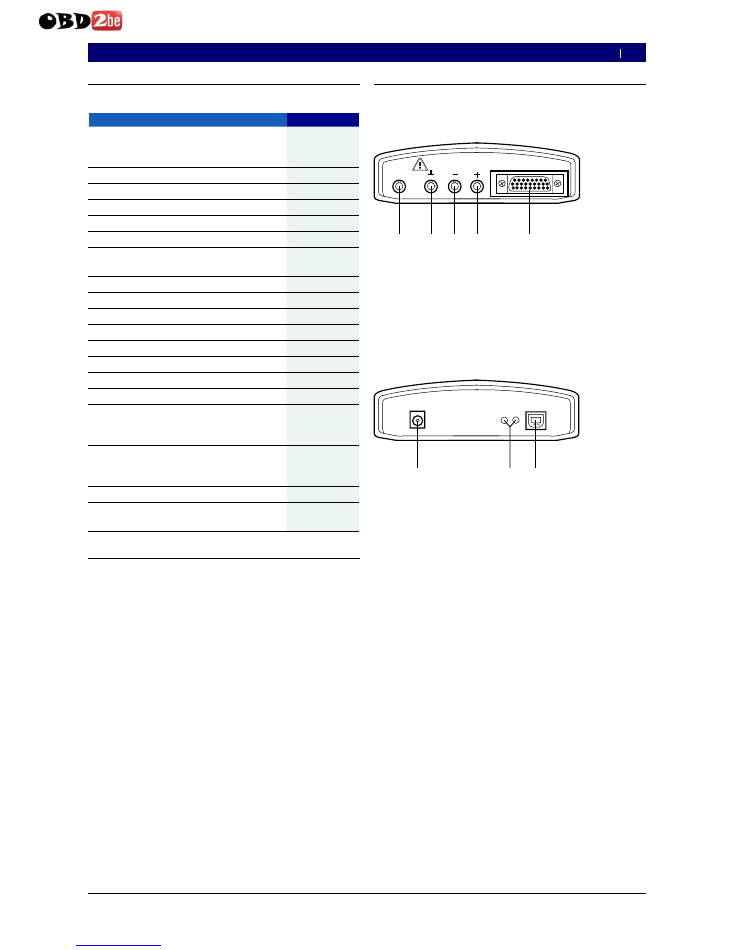
2.5.1
Diagnosis terminals/Measurement terminals
CH2
CH1
D IA G
m a x . 6 0 V
459802/12 Ko
1
2
3
4
5
F ig. 1: Diagnosis terminals/ Measurement terminals
1
M easu ring inpu t C H 2 (only for K T S 57 0 )
2
G N D soc k et
3
M easu ring inpu t C H 1(– )
4
M easu ring inpu t C H 1(+ )
5
C onnec tion O B D diagnosis c ab le (DIA G )
2.5.2
Terminal strip
15V DC
U S B
459802/11 Ko
1
2
3
A
B
F ig. 2: Terminal strip
1
P ower su pply c onnec tion
2
L E D A and L E D B (see c hap. 2.5.3)
3
U S B c onnec tion
en
http://www.obd2be.com/
Bosch Diagnostics
|
1 689 979 987
2006-09-29
18 | KTS 530 / KTS 540 / KTS 570 | Description of unit
2.5.3
Functions of L EDs A and B
L ED A
Function
Measures
Does not il-
luminate
No data communica-
tion with the controller
Check connection
with the controller
Flashes green
(irregular)
Data communication
with the controller
None
Illuminated green
Fault in hardware/
Firmware
(*)
Illuminated red
Power supply > 35 Volt. Check vol-
tage in vehicle
L ED B
Function
Measures
Does not il-
luminate
Voltage not present
Check pow-
er supply
Flashes green
(1 second in-
terval)
KTS ready for
operation
None
Illuminated green
Fault in hardware/
Firmware
(*)
Flashes yellow
(1 second in-
terval)
Overvoltage on
diagnostic cable
(*)
Illuminated yellow Fault in hardware/
Firmware
(*)
Flashes red
(irregular)
Firmware update
in operation
None
Illuminated red
Fault in firmware-
update
Repeat firm-
ware update
(*) Unplug the USB connection and power supply and connect them
again. If the error still ex ists, contact custom er service.
2.5.4
Adapter insert (IBOX 01)
The adapter insert (Fig. 3, Item 8) contains all of the
existing capabilities for establishing communication
with the vehicle diagnosis interfaces that are known. In
order to flexibly adapt to future expansions in diagnosis
protocols, the adapter insert can be changed quickly
without any tools.
KTS modules only function with the adapter insert
connected.
0
2.6
Bluetooth
2.6.1
Bluetooth USB adapter
The Bluetooth USB adapter, which is included with delivery,
allows wireless connection with KTS 540 and KTS 570. It is
connected to the PC/Laptop and shows that it is ready for
operation when the red LED is illuminated.
Do not put any mechanical stress on the Bluetooth
USB adapter and do not use it for gripping. This can
damage the laptop or Bluetooth USB adapter.
2.6.2
Information regarding Bluetooth symbols
Bluetooth Manager symbol
(in toolbar) when the
control unit diagnosis function is active::
Color
Function
Green
Bluetooth USB adapter active and
communicating with KTS 540 or KTS 570.
White
Bluetooth USB adapter plugged into PC/
laptop, but Bluetooth connection inactive.
White/
green in 7-
sec. cycle.
Bluetooth USB adapter tries to create a wire-
less connection to the KTS module.
Red
Bluetooth USB adapter not plugged into PC/laptop.
Bosch Bluetooth Device symbol
(in toolbar) when
the control unit diagnosis function is active::
Color
Function
Green
Field strength of Bluetooth wireless link OK.
Red
Field strength of Bluetooth wireless link too low.
Reduce distance between Bluetooth USB adapter
and the KTS module or avoid obstacles such
as e. g. steel doors or concrete walls.
Symbol
not there.
No Bluetooth wireless connection.
Follow the instructions in chapter 2.8.
Interrupting the Bluetooth connection with the
KTS 540 and KTS 570 can activate an acoustic alarm
signal in the PC/Laptop (see Online Help DDC). If a
fault occurs, the USB connection can be activated
and used instead of the Bluetooth connection.
0
en
http://www.obd2be.com/
Bosch Diagnostics
|
1 689 979 987
2006-09-29
Description of unit | KTS 530 / KTS 540 / KTS 570 | 19
2.7
Operation
KTS 530 can only be connected with the PC/Laptop via
the USB interface. KTS 540 and KTS 570 can be linked
with the PC/Laptop via wireless connection (Bluetooth)
or via the USB interface. Insert the Bluetooth USB
adapter in the PC/Laptop for a wireless connection.
The radio connection between KTS 540/KTS 570
and the PC/Laptop can
only
be made with the
Bluetooth USB adapter provided in the delivery.
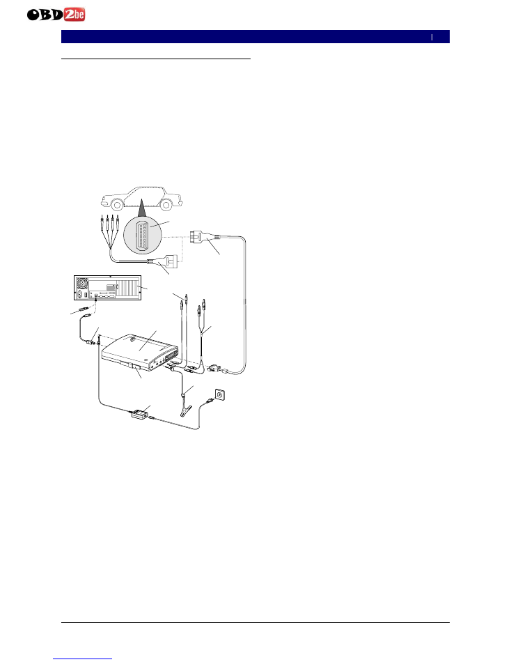
2.7.1
Connection diagram
1
2
3
4
5
6
7
8
9
10
11
12
13
14
15
16
45980
2/1 K
o
BO
SC
H
KT
S
57
0
Po
w
er
ed
by
CH
2
CH
1
DIA
G
ma
x . 6
0 V
ES
I
tro
nic
wir
ele
ss
1
3
5
9
7
8
4
B OS C H
1
0
X2 M o u s e
X1 K a y b o a rd
X25 U S B 1
X26 U S B 2
X3 C OM 1
X4 C OM 2
X7 L PT 1
X9
V
I
D
E
O
EPX
ob
en
/to
p
2
6
10
11
12
Fig. 3 : Connection diagram in an ex ample for the KTS 570
1
OBD interface in vehicle
2
UNI connection cable
3
OBD diagnosis cable
4
Measurement cables (KTS 570)
5
Measurement cables (KTS 530, KTS 540)
6
GND lead
7
Power pack
8
Adapter insert (IBOX 01)
9
KTS 570
10 USB connecting cable
11 Bluetooth USB adapter
12 PC (Laptop)
0
2.7.2
Notes concerning controller diagnosis
KTS modules are either powered via the power
supply that is delivered or through the OBD interface
of the vehicle.
In testing steps that require starting the motor, the
battery voltage may drop to a point that the supply is
no longer guaranteed via the vehicle. In these cases,
it may be required to supply the KTS module with the
power supply.
On some vehicles, the power supply through the
OBD interface may only be fed after switching the
ignition on.
The connection to the diagnosis interface in the vehicle
is made via
the OBD diagnostics cable (Fig. 3, item 3) or
the OBD diagnostics cable and the UNI connecting
cable (Fig. 3, item 2) or
the OBD diagnostics cable and a vehicle-specific
adapter line (special accessories).
The connection to the diagnosis interface in the ve-
hicle takes place via the OBD-diagnosis cable (Fig. 3,
Pos. 3) or additionally via the UNI-connection cable
(Fig. 3, Pos. 2) and vehicle-specific adapter cables
(special accessories).
Notes on controller diagnosis can be found in the
Online-Help.
0
R
R
R
0
en
http://www.obd2be.com/

Bosch Diagnostics
|
1 689 979 987
2006-09-29
20 | KTS 530 / KTS 540 / KTS 570 | Description of unit
2.7.3
Notes concerning the multimeter and
oscilloscope
Danger from high voltage!
If measurements are tak en without a
ground lead, potentially deadly voltages can
be generated.
If no diagnosis cable is connected, a
ground connection is to be made from
the KTS modules before making any V-, R-
or I-measurements (Fig. 1, Item 2) made
connection to vehicle ground with the
ground cable provided!
Connect the ground cable as close as
possible to the measurement object!
Use KTS modules only on the vehicle and
not for measurements for voltages > 60 volts!
Do not perform any measurements on
ignition systems!
Only use the accompanying measuring
cables with touch protection!
Always insert measuring cables in the
KTS modules first and then into the vehicle!
Do not route unshielded measuring cables
close to high-power sources of interference,
such as e.g. ignition cables!
To prevent KTS 570 failure, before calling menu
point "
Oscilloscope
", measurement input CH1(–)
must be connected with vehicle ground. In menu
point "
Oscilloscope
", measuring input CH1(–) and
measuring input ground are connected internally
(floating measurement, see chap. 5.5 ).
2.7.4
Firmware update
After an update of ESI[tronic], the firmware of
the KTS modules is updated automatically when the
controller diagnosis is started.
To update the firmware, supply the KTS module
using the supplied power supply and connect to the
PC/Laptop using the USB connection cable. During
the firmware update, the USB connection is not to
be interrupted. The firmware update can also be
done using DDC (Diagnostic Device Configuration)
(see Online help DDC).
The firmware update must always be done using the
USB connection cable (not via Bluetooth) with the
KTS 540 and KTS 570.
2.8
Notes concerning faults
2.8.1
Diagnosis hardware has not been found.
When the control unit diagnosis software was started
or during communication with the control unit, no dia-
gnosis so diagnosis hardware (KTS module) was found.
The fault message "
Connect diagnosis hardware and
supply it with ex ternal voltage
" or "
Wireless connec-
tion to the KTS module is faulty
".
P ossible causes
What can you do
No external vol-
tage supply.
Check whether the KTS module has
an external voltage supply (pow-
er pack or OBD diagnostics cable).
LED B on the KTS modu-
le must be flashing green.
KTS module not
active or incorrect-
ly configured.
1. Terminate ESI[tronic] and
control unit diagnosis.
2. Start the DDC ("Start >> Set-
tings >> Control panel").
3. In the DDC, check whether the
KTS module is correctly confi-
gured and has been activated.
4. Finally, test the KTS module.
Bluetooth connection
faulty or non-existent.
Bluetooth manager symbol
flashing white or white/green
1. Reduce the gap between
the Bluetooth USB adap-
ter and the KTS module.
2. Test the KTS module in the DDC.
3. If the Bluetooth connection does
not test OK, initialize Bluetooth
drivers (see Chapter 2.8.3).
4. Reboot PC/laptop.
No Bluetooth USB
adapter.
Bluetooth manager symbol
red
1. Plug in the Bluetooth USB adapter.
2. Re-start the control unit diagnosis.
2.8.2
No communication with the control unit
During the control unit diagnosis, the following fault
message appears: "
No communication with the control
unit. Adapter lead connected?
"
P ossible causes
What can you do
Incorrect lead
connected.
Check if the correct lead has been used.
Incorrect PIN se-
lected in the mul-
tiplexer menu.
Consult the SD Help function to
see which PIN must be used.
Measures for other possible faults are described in
chapters 1.6, 2.5.3 and 2.6.2.
If problems of a different nature occur, please con-
tact the ESI[tronic] service hotline directly.
0
en
http://www.obd2be.com/
Bosch Diagnostics
|
1 689 979 987
2006-09-29
Description of unit | KTS 530 / KTS 540 / KTS 570 | 21
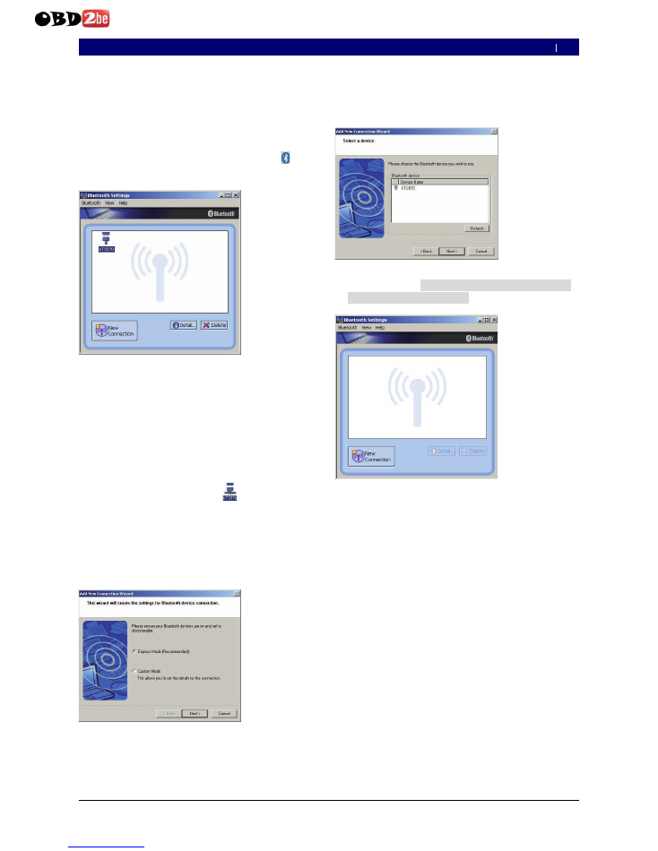
2.8.3
Initializ ing Bluetooth drivers
If the Bluetooth connection is faulty or absent or alter-
native remedial measures failed (see Chapter 2.8.1),
the Bluetooth drivers must be initialized.
Proceed as follows:
Double-click on the Bluetooth manager icon .
Bluetooth settings will open
If the "
Add New Connection Wiz ard
" dialog win-
dow opens, continue from Item 4.
Check whether a KTS module appears under the
entered Bluetooth devices.
If no KTS module is entered: select <
New connec-
tion
> and then proceed from Item
or
If a KTS module is entered: delete KTS module.
If KTS module is connected
: Select
"
Bluetooth > > Disconnect
" menu option.
Select "
Bluetooth > > Delete
".
Select <
New connection
>.
"
Add new Connection Wiz ard
" dialog window will
open.
1.
?
0
2 .
3 .
3 .
I
I
I
?
Select
Express mode
option.
Select <
Next
>.
Bluetooth devices will be searched and displayed.
Select <
Cancel
>.
Confirm prompt
Are you sure you want to
close the Assistant?
with <
Y es
>.
In the "
Bluetooth settings
" dialogue window, select
"
Bluetooth > > Terminate
".
Bluetooth drivers are now initialized.
4 .
5 .
?
6 .
7 .
8 .
G
en
http://www.obd2be.com/
Bosch Diagnostics
|
1 689 979 987
2006-09-29
22 | KTS 530 / KTS 540 / KTS 570 | Initial start-up
3.
I nitial start-up
Do not plug in the Bluetooth USB adapter until
req ues ted to do s o during ins tallation of the Blue-
tooth driv er on y our P C or laptop
(Message: Connect
Bluetooth device).
If the Bluetooth USB adapter is plugged in too soon, the
Windows hardware assistant is opened. The Windows
hardware assistant must be terminated and the Blue-
tooth USB adapter removed.
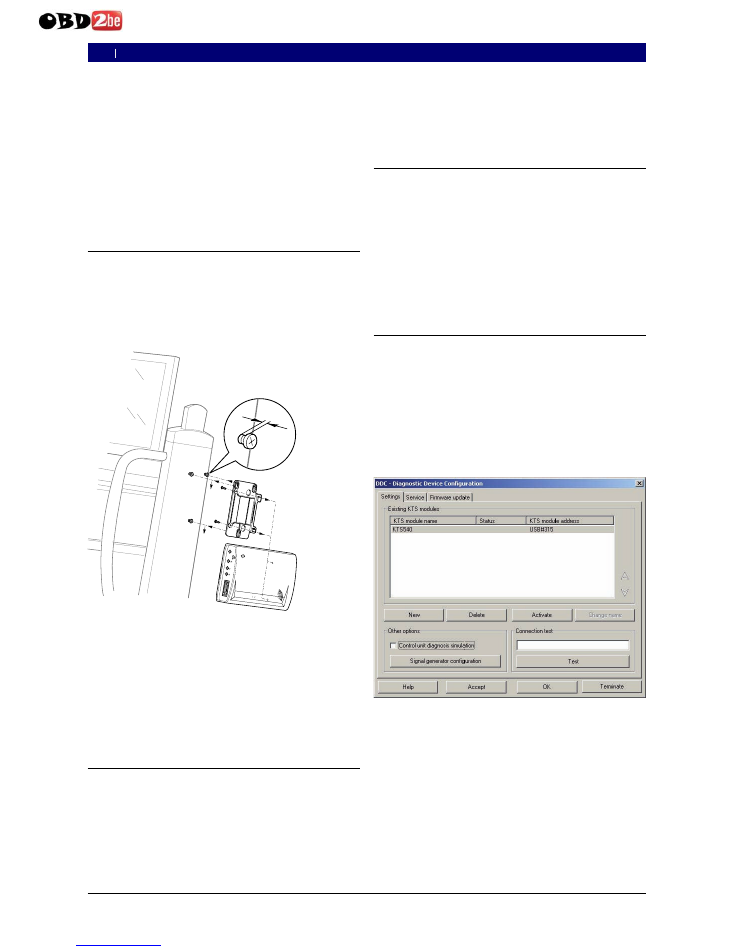
3.1
Assembly mount
The mount included with the delivery allows fastening
and loosening the KTS modules on the Bosch trolley
(possible as of production date 03-2006 only).
Screw in the three fillister head screws on the Bosch
trolley (see Fig. 4).
BOSCH
C
H
2
C
H
1
D
IA
G
m
a
x
. 6
0
V
K T S 5 7 0
P ow e r e d b y E SI tron
ic
wireless
45980213
2 m m
Fig. 4
A ssembly mount
Using the sheet-metal screws included with the de-
livery, screw the mount onto the KTS module (holes
for mounting are on the rear of the module).
Correct the screw penetration of the fillister head
screws on the vehicle so that the KTSmodules are
solidly and securely seated in position following instal-
lation.
3.2
ESI[ tronic] software installation
ESI[tronic] 2006/3 U* (with blue U*).
Depending on the type of installation selected, you
will be asked to insert ESI[tronic] 2006/1 during the
installation.
1.
2.
3.
1.
0
If the ESI[tronic] has not been enabled yet, enable it now.
How to install and enable the ESI[tronic] is described
on the "ESI[tronic] DVD 1 Diagnosis and technology"
in the directory '
DOCS\ S
ETUP\ IN F O _ X X X .PD F
'.
3 .3
C o n n e c t io n
C o n n e c t th e K T S m o d u le w ith th e p o w e r s u p p ly
in c lu d e d w ith th e d e liv e r y .
C o n n e c t th e K T S m o d u le w ith th e P C / L a p to p u s in g
th e U S B c o n n e c tio n c a b le .
T h e m e s s a g e " F o u n d n e w h a rd w a re " w ill a p p e a r
o n th e s c re e n th e firs t tim e th a t th e K T S m o d u le s
a re c o n n e c te d u s in g th e U S B c o n n e c tio n c a b le .
T h is in d ic a te s th a t th e U S B c o n n e c tio n to th e
K T S m o d u le s h a s b e e n re c o g n iz e d .
3 .4
C o n fig u r a t io n ( D D C )
T h e fu n c tio n o f th e D D C ( D ia g n o s tic D e v ic e C o n fig u -
r a tio n ) s o ftw a re is to c o n fig u re , a c tiv a te a n d te s t th e
K T S m o d u le s .
S ta r t th e D D C ( "
Start >> Settings >> Control
p anel
" ) .
C o n fir m th e D D C fa u lt m e s s a g e w ith <
O K
> .
A lw a y s re m o v e th e s a m p le e n tr y "
K T S 5 4 0
" .
A d d th e K T S m o d u le v ia "
N ew
" .
O th e r p ro c e d u re s fo r c o n fig u r a tio n c o n c e r n in g th e
in itia l s ta r t-u p a re d e s c r ib e d in th e o n lin e h e lp . U s e
<
H e lp
> to o p e n th e o n lin e h e lp . A ll o th e r im p o r ta n t
in fo r m a tio n c o n c e r n in g D D C is fo u n d h e re a s w e ll.
If y o u h a v e a n y q u e s tio n s w h ic h c a n n o t b e a n s w e re d
b y th e o n lin e H e lp , p le a s e c o n ta c t th e E S I[ tro n ic ]
s e r v ic e h o tlin e d ire c tly .
2.
0
1 .
2.
0
0
1 .
2.
3 .
4 .
0
0
e n
http://www.obd2be.com/

Bosch Diagnostics
|
1 6 8 9 9 7 9 9 8 7
2 006 -09 -2 9
Maintenance | K TS 5 30 / K TS 5 40 / K TS 5 7 0 | 23
4.
M a i n t e n a n c e
4.1
Cleaning
The housing of the KTS modules are only to be cleaned
using a soft cloth and a neutral cleaning agent. Do not
use any abrasive cleaning agent or rough cleaning cloths.
4.2
Maintenance
The tab
Cu stom er serv ice
can be used for performing
various tests in DDC. A portion of these tests can only
be performed by customer service.
4.3
S pare and w earing parts
R eplacement and wear parts only concern parts
received in the respective delivery.
Des cription
Ord er Num b er
System tester KTS 5 3 0
1 6 8 7 0 2 2 4 3 7
System tester KTS 5 4 0
1 6 8 7 0 2 2 4 3 6
System tester KTS 5 7 0
1 6 8 7 0 2 2 9 9 4
Adapter insert
1 6 8 8 0 0 0 3 4 9
OBD diagnosis cable 3 m (KTS 5 3 0 )
(<)
1 6 8 4 4 6 5 5 5 7
OBD diagnosis cable 1 .5 m (KTS 5 4 0 /5 7 0 )
(<)
1 6 8 4 4 6 5 5 5 5
Power pack
Power supply cable
(<)
1 6 8 7 0 2 2 8 8 9
1 6 8 4 4 6 1 1 0 6
M easuring cable blue (KTS 5 3 0 /5 4 0 )
(<)
1 6 8 4 4 3 0 0 6 6
M easuring cable yellow (KTS 5 3 0 /5 4 0 )
(<)
1 6 8 4 4 3 0 0 6 7
G round cable black
(<)
1 6 8 4 4 3 0 0 6 8
M easuring cable red/black (KTS 5 7 0 )
(<)
1 6 8 4 4 6 3 2 1 4
M easuring cable blue/yellow (KTS 5 7 0 )
(<)
1 6 8 4 4 6 3 5 5 0
Test tip red (1 x , with KTS 5 7 0 2 x )
1 6 8 4 4 8 5 0 3 5
Terminal clip black
(<)
1 6 8 4 4 8 0 0 2 2
Connection cable USB 3 m
(<)
1 6 8 4 4 6 5 5 6 2
UN I connection cable 4 core
(<)
1 6 8 4 4 6 3 5 3 9
Case
1 6 8 5 4 3 8 1 4 5
M ount parts set
1 6 8 7 0 0 1 8 5 3
Bluetooth USB adapter (KTS 5 4 0 /5 7 0 )
1 6 8 7 0 2 3 3 8 2
(<)
P a r t s u b je c t to w e a r
0
5 .
T e c h n i c a l d a t a
5 .1
G eneral d ata
Property
V alue/ R ange
Operating voltage
7 V DC — 3 0 V DC
Power consumption through
vehicle battery or power supply
approx . 6 W att
Dimensions (L x W x H)
1 7 0 x 1 2 0 x 4 0 mm
W eight (without connecting cables)
3 2 5 g
Operating temperature
0 ° C – 4 0 ° C
R elative humidity
9 0 % (at 2 5 ° C)
5 .2
Interface protocols
The following interfaces with respective protocols are
supported for controller diagnosis in conformance with
ISO 1 5 0 3 1 :
ISO 9 1 4 1 -2 (Communications lines K and L)
SAE J 1 8 5 0 V PW and SAE J 1 8 5 0 PW M
(Communication lines BUS+ and BUS-)
CAN ISO 1 1 8 9 8 ISO 1 5 7 6 5 -4 (OBD)
(Communication lines CAN -H and CAN -L)
CAN Single W ire
CAN Low Speed
5 .3
Pow er pack
Property
V alue/ R ange
Input voltage
9 0 — 2 6 4 V AC
Input frequency
4 7 — 6 3 Hz
Output voltage
1 5 V
Operating temperature
0 ° C — 4 0 ° C
5 .4
Multim eter s pecifications
CH1 zero potential (blue input is not allowed to be
connected with voltage carrying measuring points).
Input resistance > 9 0 0 k Ohm.
CH2 potential based (black ground input
must be connected with vehicle ground).
Input resistance > 9 0 0 k Ohm.
5 .4.1
DC m eas urem ent (CH1 and CH2)
Property
V alue/ R ange
M easurement range
2 0 0 mV — 2 0 0 V
Precision CH1
± 0 .7 5 % of measurement value,
additional ± 0 .2 5 % of measurement range
Precision CH2
± 2 % of measurement value,
additional ± 0 .5 % of measurement range
R esolution
1 0 0 µ V — 1 0 0 mV
(depending on measuring range)
R
R
R
R
R
R
R
en
http://www.obd2be.com/

Bosch Diagnostics
|
1 689 979 987
2006-09-29
24 | KTS 530 / KTS 540 / KTS 570 | Tech nical data
5.4.2
A C and effectiv e v alue measurement
(CH1 and CH2)
* )
Property
Value/Range
Frequency range AC
10 Hz — 400 Hz (-3 dB)
Measurement range
200 mV — 200 V
AC precision at 100 Hz
EFF precision at ≤ 100 Hz
±2 % of measurement
value, additional
±0.5 % of measurement range
Resolution
100 µV — 100 mV
(depending on measuring range)
*)
T h e m easurin g ran g es an d ty p es of m easurem en t "U " an d "I" are
p eak -to-p eak v alues. T h is results in th e d ig ital d isp lay field bein g
g ray ed out as soon as th e d efin ed m easurin g ran g e h as been
ex ceed ed for a sh ort tim e (O v erload ).
5.4.3
Resistance measurement (CH1)
Property
Value/Range
Measurement range
100
U
— 1 M
U
Precision up to 200 K
U
±0.75 % of measurement value
additional ±0.25 % of
measurement range
Precision up to 1 M
U
±2 % of reading
additional ±0.25 % of
measurement range
Resolution
0.1
U
— 1000
U
(depending on measuring range)
Input resistance
> 9 M
U
5.4.4
Current measurement (CH1 and CH2)
sensor
Measurement range
Shunt (CH1 only)
±600 mA
30 A clamp (CH1 only)
±30 A
100 A clamp
±100 A
600 A clamp
±600 A
1000 A clamp (CH1 only)
±1000 A
5.4.5
Continuity tester (CH1)
Property
Value/Range
Measurement current
2 mA
Open circuit voltage
≤ 5 V
Continuity
< 10
U¤
(with acoustic response)
5.4.6
Diode measurement (CH1)
Property
Value/Range
Measurement current
2 mA
Open circuit voltage
≤ 5 V
Maximum diode voltage
2 V
5.5
Oscilloscope specifications
CH1 and CH2 are potential based
(Measuring input CH1(–) or measuring input
ground must be connected to the vehicle ground).
Input resistance > 900 kOhm.
Property
Value/Range
Measurement range
0 — 200 V
Coupling
DC, AC,
DC(+) (only positive range is shown),
DC(-) (only negative range is shown).
Signal source
U, 30 A (CH1 only), 100 A,
600 A, 1000 A (CH1 only),
Diagnosis pins 1 to 15
(not pins 4, 5)
X -deflection
50 µs — 1 s
Trigger mode
Manual, Auto-Time, Auto-Level
Trigger source
CH1, CH2
Pretrigger time
0 — 80 %
Frequency range
> 1 MHz (typical 5 MHz)
Memory depth per channel
50 signal curves with
512 coordinates
5.6
B luetooth Class 1
W ireless connection
KTS 540, KTS 570 to PC/L aptop
Minimum range
Workshop environment in the open
space
30 meters
If the vehicle door or window is open
and the engine is still running in the ve-
hicle interior
10 meters
R
R
en
http://www.obd2be.com/