Full Text Searchable PDF User Manual

- 1 -
Blue 5c
Audio Console
User Manual
Effective March 30, 2001
Model: 2505
5 Channel Stereo Console

- 2 -
BLUE 5c CABLE OPTIONS
RJ45 cable
Six-foot length of cable terminated with RJ45 plug on
one end and open leads on the other.
May be used for both audio inputs and outputs of the
Blue5c console.
B500
$5.00
Qty
_____
Mic Input Beissel
Mic input (pre-amp) cable.
Used to bring Mic audio up to approx. 0 db.
Adjustable for Mic level of –45 to –65 db.
Four-foot cable with female XLR to RJ45 plug.
(48V Phantom power NOT available)
B510
$75.00
Qty
_____
Line Input Beissel
Consumer to Pro (line level) input cable.
Used to bring consumer audio levels up to approx. 0db.
Provides 10db audio boost plus an additional 6 db.
variable adjustment independent left and right.
Six-foot cable with male RCA’s to RJ45 plug.
B520
$75.00
Qty
_____
Pro Input Beissel
Balanced audio input cable.
Used to connect Pro level (0db) source equipment to
the Blue5c.
Six-foot cable with female XLR’s to Balanced RJ45
plug.
B530
$20.00
Qty
_____
Pro Output Beissel
Balanced audio output cable.
Used to connect the output of the Blue5c to any
external device requiring XLR connectors.
Six-foot cable with RJ45 plug to Balanced male XLR’s.
NOTE: Console Output is +4db nominal
B570
$20.00
Qty
_____
Credit Card Order
TOTAL
Please circle credit card choice and complete all areas of information in order to ensure
proper processing of your order.
American Express Visa MasterCard Novus Diners Club Discover
Credit Card Number
Card Expiration Date:
Name On Card:
Card Billing Address:
Shipping Address:
City, State, Zip:
Contact Person:
Contact Phone:
I authorize LPB Communications to charge my credit card for the amount of U.S. Dollars for
the above indicated items as well as applicable freight charges.
Cardholder Signature:
FAX TO (610) 644-8651

- 3 -
Section 1 - Introduction and General Information
1.1
Blue 5c Audio Console
Congratulations on choosing an LPB Blue 5c audio mixing console. Blue has combined the
operational features of an ON AIR board with mobility and quick installation needed in both editing
and remote operations. The small size and low cost also are something new to the market.
Blue is intended for use in both professional and non- professional broadcast applications, including
radio, audio production, remotes, standard and low-power broadcast television as well as cable
television. Its flexible features, simplicity and excellent specifications extend its potential into
allied fields, such as small sound reinforcement systems and recording studios. Blue is an ideal
choice in any application requiring superior audio performance, rugged, long-term reliability, ease
of maintenance and simple, straightforward operation.
1.2
Console Configuration
Blue is a simple five channel console with stereo linear faders. Each of the five faders has two
stereo inputs. Input 1 & 2 for channel one, input 3 & 4 for channel two and so on. Input audio is
inserted into the console through RJ45 connectors located on the rear of the unit. There are ten
positions respective to inputs 1 through 10 and two stereo output connections for Program and Cue.
The DB25 pin connector located on the rear panel provides contact points for remote start tally’s for
all 10 inputs, Send bus audio, Program and Cue metering, On Air light tally as well as +/- 15VDC
and Ground. A 10 position DIP switch is located on the rear panel. When a switch is enable, the
respective ON switch, when depressed, will actuate the ON AIR Light tally on the DB25 and the
console ON AIR symbol will light as well. Studio monitor audio feeds are provided on the rear
panel by two balanced ¼ “ phone jacks. Level control is provided by a fader control located on the
right side of the console. Two separate headphone jacks and controls are located on both the left and
right front corners of the unit on ¼ “ phone jacks. A switch selecting either Program of Cue as well
as a level pot are provided.
FOR DETAILED CONNECTOR INFORMATION SEE THE
INSTRUCTION LABEL LOCATED ON THE BOTTOM OF THE CONSOLE

- 4 -
Section 2 - Warranty
Blue 5c Warranty Information
LPB Communications warrants its Blue 5c Audio Mixing Consoles to be free of defects in materials
and workmanship for a period of 2 years from date of original shipment and excludes wear items
such as indicators, fuses, etc. Assemblies obtained by LPB Communications from other
manufacturers for use in Blue, such as faders and switches, carry a warranty only as stated by the
original manufacturer, typically one (1) year, and LPB Communications assumes no other liability.
LPB Communications assumes no liability for damage to product incurred in shipment or handling.
To establish the validity of the warranty, warranty registration forms included with the product at
time of shipment must be completed and submitted to LPB Communications at time of receipt by
the original purchaser. Failure to do so may invalidate any or all portions of the warranty.
The warranty is limited to malfunctions or defects discovered in the course of normal and correct
usage and/or maintenance of the product. Damages due to abuse, user misalignment, lack of
proper maintenance, usage or maintenance outside that prescribed in the Service Manual for the
product, mains voltage fluctuations or excursions, exposure to the elements, or acts of God, are
not covered under this warranty. Modification or alteration of the product by any party other than
LPB Communications causes this warranty to be null and void.
Warranty claims will be honored only through the established procedures of LPB Communications.
Product may be returned only following written notification to LPB Communications within thirty
days of the discovery of a malfunction or defect, and then only by utilizing LPB Communications
Material Return Authorization (MRA) system and procedures. LPB Communications reserves the
right, at its option, to repair, replace, or refund the original purchase price of defective product. LPB
Communications assumes no liability for shipping, handling, insurance, duty, or tariff fees incurred
in connection with the support of this warranty.
The full extent of the purchaser rights and remedies are stated above. No other warranties
expressed or implied by any third party is binding on LPB Communications. LPB Communications
assumes no liability for incidental or consequential damages arising from the use, or inability of
use, of this product.

- 5 -
Section 3 - Specifications
Input:
Input Impedance:
Line 10,000 ohm bridging
Levels:
Line, 0 dbm
Output:
Program
Transformer Isolated, 600 ohm, +4dbm
Cue & Send
Active Balanced Bridging, 10,000 ohm, 0dbm
Frequency Response:
Line, 20 - 20 kHz ± 0.5 dbm
Noise:
Line, better than -80 dbm, 20 - 20 kHz
Crosstalk/Muting:
Better than 70 dbm between any outputs @ 1 kHz
Harmonic Distortion:
Less than 0.03% THD, 20 - 20 kHz
Intermodulation Distortion:
Less than 0.03% SMPTE
Note: Output measurements referenced to +4 dbm nominal output level
AC Line Input
100/120/220/240 VAC, 47-63 Hz
Physical Characteristics:
Height: 3.5”
Depth: 12.5”
Width: 16.5"
Weight: 5.25 lbs.
- 6 -
Section 4 - Installation
4.1
Unpacking
BEFORE UNPACKING, INSPECT THE SHIPPING CONTAINER FOR ANY EXTERNAL EVIDENCE OF
SHIPPING DAMAGE
. Document any external damage in writing, and/or photograph it before opening the
carton. If the damage is extensive, notify the carrier before opening.
SAVE THE CARTONS AND ALL PACKING MATERIAL UNTIL THE EQUIPMENT IS COMPLETELY
INSTALLED AND OPERATING SATISFACTORILY
. If hidden shipping damage is found upon opening the
cartons, notify the carrier and LPB Communication at once. The carrier will want to inspect the shipping
carton and packing materials. Federal regulations require freight claims to be filed by the recipient of the
shipment. Failure to file a claim with the shipper in a timely manner may result in a claim denial.
4.2
Inspection
If you ordered any optional items, such as the B series of cables, make sure they are present. Contact the LPB
Customer Service Department if any discrepancies are found. This is a good time to complete and return
your Warranty Registration Form.
4.3
Grounding Information
Proper grounding is the most critical part of any console installation. In addition to being electrically
hazardous, improper grounding can severely degrade the operation of the console and the entire studio. DO
NOT PROCEED WITH INSTALLATION UNTIL YOU HAVE A GROUNDING PLAN THAT
SATISFIES THE REQUIREMENTS OF YOUR LOCAL ELECTRICAL CODES AND ACCEPTABLE
AUDIO PRACTICES. If you are not experienced in designing grounding systems for audio studios, consult
with an experienced professional.
The goal of any audio grounding system is to provide proper grounding for all equipment while avoiding
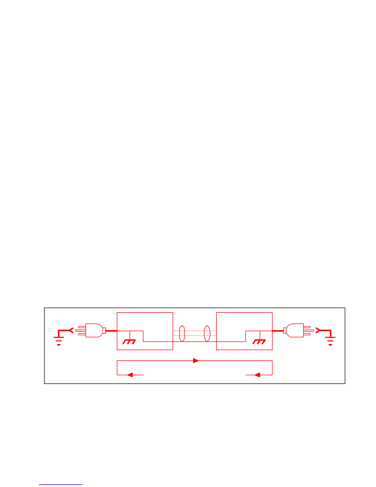
ground loops. A ground loop is present any time a piece of equipment has two or more paths to ground (See
Figure 4.1). For example, if a tape machine is connected to ground through the grounding prong of the AC
line cord and by the shield connections of its audio lines, a ground loop exists.
Shield
Audio Line
Ground Loop
AC Power
Device A
Device B
AC Power
Figure 4.1
Ground loops often cause noise in the system, usually in the form of 60 or 120 Hz hum or buzz, and may
induce RF interference. To eliminate a ground loop, all paths to ground must be severed, except one
(preferably the AC safety ground). NOTE: AUDIO SHIELDS DO NOT PROVIDE AN ACCEPTABLE
AC SAFETY GROUND. Clipping off the grounding prong on the AC plug, or using a 2-prong plug adapter,
and grounding the machine by way of its audio shields only, is extremely unsafe, with potentially lethal
consequences.
- 7 -
It is standard practice to ground all input shields at the console end of the line, and leave the shield
disconnected at the source equipment end. Console output shields are normally left open at the console end,
and grounded at the load end. The AC safety (chassis) grounds of all external equipment (as well as the
console's) should be returned to the same physical and electrical point in the studio for optimum operation.
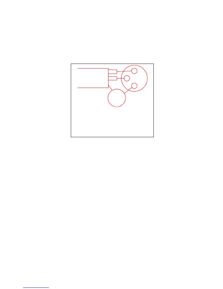
In areas of intense RF interference, shields with one end un-terminated may pick up RF and radiate it into the
console. In this case, the open end of the shield should be connected to ground with a small 0.1 ufd capacitor
(see Figure 4.2); the capacitor will act as a short to RF frequencies, but will appear as an open circuit at 60
and 120 Hz.
Special care should be taken when integrating equipment with unbalanced (consumer) inputs and outputs
into the system. Much of this equipment has no provisions for chassis grounding at all. In this case, one
audio cable shield must be terminated at both ends, or the audio circuit will not work for lack of a ground
reference. If you are using the LPB B520 Line Input Beissel, do not add grounding to the consumer
equipment. Unbalanced equipment with a grounded chassis (such as some professional power amplifiers)
should be installed normally, i.e., with shields open at the console end, and the chassis returned to ground by
a grounding cable. Alternatively, an isolation transformer may be used at the input of the unbalanced device.
Some devices feature a ground link or jumper for strapping the chassis ground to the audio ground. Be sure
these links are connected in accordance with your grounding plan.
The console and all external equipment are usually grounded to a grounding bus, or copper strap, with an
individual grounding conductor, such as copper wire, strap or braid. The grounding bus is securely
connected to an effective electrical ground.
the open end of the shield.
capacitor from shield to ground at
connect a compact ceramic disc
may pick up RF. To avoid this
presence, shields left open at one end
heavy RF
In areas of
mfd
0.1
Shield
-
+
Figure 4.2
- 8 -
4.3.1 Grounding the Console
1
ON
2 3 4 5 6 7 8 9 10
AUDIO INPUTS 1 - 10
C U E
OUT
PGM
OUT
1
2
3
4
5
6
7
8
9
10
Ground
Power
Supply
MONITOR
AUX & LOGIC OUTPUTS
MUTING
L
R
OUTPUTS
1
13
14
25
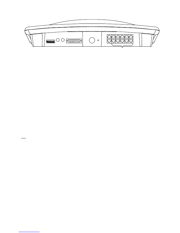
A grounding lug is provided on the rear of the console.
Connect the console grounding wire to the central grounding point for the studio. Do not count on metal
cold water pipes as a console grounding point, as the use of plastic pipe and fittings or Teflon tape elsewhere
in the line may place the pipe above ground potential. Also, condensation on cold water pipes can corrode
ground connections.
It is also best to avoid the facility AC power ground as a grounding point, especially in old construction.
While adequate for safety purposes, it may have a small voltage potential, and serve as a source for electrical
noise in the system. In new construction, early consultation with the electrical contractor can result in an AC
grounding system that is adequate for audio purposes.
One final tip: Remember that metal equipment racks also provide a grounding path for any equipment
mounted in them. This can be useful, as all equipment in a rack can be grounded via a single bus wire.
However, it is easy to presume that a piece of rack mounted equipment is grounded only by its AC connector,
when in fact it sees a second path to ground through the rack itself, thus creating a hidden ground loop.
4.4 Connecting the Power Cord
We highly recommend the use of an external surge suppresser to reduce the possibility of damage caused by
lightning and other transients on the AC power line.
Insert the power supply plug into the rear of the console labeled POWER. Plug In the AC power cord. The
ON switches located on the console should be illuminated when pressed. DO NOT PROCEED IF THESE
LAMPS FAIL TO ILLUMINATE. If you find this condition, check for AC at the wall outlet feeding the
power supply. If this step does not restore normal operation then proceed no further. Call the LPB Customer
Service department immediately.
Upon verification that power is available to the console, installation of the audio input, output and logic
circuits can begin.
4.5
Audio Input Wiring
Tools required for installation include a soldering iron, RJ45 crimp tool and a small-gauge wire
stripper/cutter. A heat gun is recommended so that the ends of all jacketed cables can be served with heat-
shrink tubing.
The console wiring diagram should be drawn out ahead of time, for fastest installation, with all wires and
connectors clearly designated. Professional installation practices recommend that wires, cables and
connectors be numbered or labeled at the time of installation to match the wiring diagram. Wire ties, cable
brackets and other accessories also should be on hand prior to installation.
All audio inputs to the console are located at the rear of the console on an RJ45 connector.
Note that the nominal input audio input level for this console is 0 dbm. This level is typical of professional
audio equipment, however, consumer equipment often provides between –10 and –15 dbm of audio.

- 9 -
Consumer equipment generally uses un-balanced connections such as RCA and phone jack connectors. Quite
simply balanced audio has three connections, a Plus, Minus and Ground (or shield). Un-balanced audio has
two connections - Plus and Ground.
For your convenience a console will arrive with one MIC INPUT cable (B501), one LINE INPUT cable
(B502) and 4 RJ45 to open leads (B500) which may be used for inputs and outputs.
With so many optional connections in both the professional and consumer audio market, it is impossible to
provide cabling to meet every individual need. We have provided a sampling of the cables, which are
available as options.
RJ45 jacks contain eight wires each. Six of these are used for balanced audio input and the other two provide
+/- 15 VDC to the B series of input amps. (see inside front cover)
The input wiring is clearly labeled on the bottom cover of the unit and are identical for each mixer (see the
console outline drawing for general location).
REMEMBER: There is +/- 15VDC present on the RJ45 Connections. PLEASE check all diagrams before
wiring your own cables.
4.5.1 General Installation Comments
Connect one audio source at a time, and check for RF interference and other problems before proceeding. It
is advisable to connect a sensitive voltmeter or oscilloscope to the console Program output to monitor signal
quality as each input is connected to the console. Any noticeable degradation in the console's noise floor
should be investigated and eliminated before moving on to the next input.
Remember that FM RF interference usually is caused by rectification of a high RF signal level; AM RF
interference usually is caused by a system ground loop (see Section 4.4). Telephone lines are often the cause
of noise problems, and a 600:600 ohm isolation transformer is recommended at the console input for direct
connection to the phone line. In high RF fields, proper grounding techniques are absolutely necessary.
Important: Never apply a phone line directly to the console. The presence of a ring voltage will cause
damage to the circuitry.
4.5.2 Wiring the Inputs and Outputs Using the B500 Cable
RJ45 wiring is standard T568B and should be readily available at your local computer or phone supply store.
LPB offers a series of pre-made input cables and amplifiers. Information is located on the inside of the front
cover of the manual.
Pin 1
White/Orange
Left +
Pin 2
Orange/White
Left –
Pin 3
White/Green
Right +
Pin 4
Blue/White
GND
Pin 5
White/Blue
GND
Pin 6
Green/White
Right –
Pin 7
White/Brown
-15VDC
(not available on B500 Cables)
Pin 8
Brown/White
+15VDC
(not available on B500 Cables)

- 10 -
4.5.3 Microphone Inputs
Microphone inputs must first be brought up to Line level (0dbm). This is possible in a number of different
options. The easiest option is to use the B510 Mic pre-amp Beissel provided with Blue.
If you have a need for more than one Mic input at a time you may order more B510’s or use an external Mic
pre-amp or Mic processor as well.
NOTE: Ensure that external amps provide the Mic audio to both left and right channels. Some amps simply
amplify the Mic audio however they do not add the audio to both left and right inputs.
4.5.4 Phantom Power
Blue is not fitted with a phantom power supply.
Using Mics with this requirement also require an external Phantom Mic power supply.
4.5.5 Line Level Inputs
Line level input sources may be mono or stereo. Low impedance, mono input sources should be paralleled
across both left and right inputs. Care should be taken to avoid an impedance mismatch with high impedance
mono sources. An impedance matching transformer or a resistive splitter network may be used. Observe
correct polarity, and connect the shield to the adjacent frame ground pin.
Unbalanced equipment should be connected with careful attention to the grounding problems discussed in
Section 4.4. The "hot" wire is usually connected to the plus input terminal, and the shield is connected to
BOTH the minus input terminal and signal ground.
4.6
Audio Output Wiring
Program and Cue audio outputs from the console are on the RJ45 connector panel located on the rear of the
unit. See the label on the bottom cover of the unit for directions.
The
Program
output is factory set to +4 dbm and is based on nominal input levels of 0 dbm.
The
Cue
and
Send
outputs are factory set to 0 dbm and are based on nominal input levels of 0 dbm.
To adjust the mixer gain, set the fader to its normal operating position and select an input. Adjust the pot for
the respective output located on the bottom cover of the unit. Program output is capable of +8 dbm. Cue and
Send outputs are capable of +4 dbm.
The Program Output is a 600 ohm transformer balanced output. The Cue and Send outputs are active
balanced at 10K ohm impedance. Program standard output level is +4 dbm. Cue standard output is 0 dbm.
Observe proper and consistent polarity when connecting output lines, and be sure to avoid bundling output
cables with input cables (especially mic level cables).
4.6.1 Connecting Outputs to Unbalanced Equipment
Blue features both transformer and active balanced output circuitry; in other words, the (+) and (-) terminals
of the active balanced output are driven directly by a pair of output amplifiers, and no output transformer is
used. While these outputs can be connected to balanced loads just as transformers, their connection to
unbalanced equipment should be undertaken with care.
The "hot" connection of the unbalanced equipment should be connected to the output's (+) terminal, and the
(-) terminal of the output should be left unconnected. GROUNDING THE (-) TERMINAL OF THE
OUTPUT MAY DAMAGE THE OUTPUT AMPLIFIER.
Most unbalanced equipment is consumer-grade, with a chassis that offers no provisions for grounding. In
this case, it is possible to connect the "shield" connection of the unbalanced equipment directly to console
- 11 -
ground without inducing a ground loop. It should be noted that the maximum output level will drop by 6
dbm in the unbalanced mode, since half of the output voltage has been effectively eliminated. This is not
usually a problem, as most unbalanced audio devices have very sensitive inputs and do not require a large
drive voltage.
Where the unbalanced equipment has a connector for chassis grounding, the preferred method is to leave the
cable shield unconnected at the console, and connected to the shield terminal of the unbalanced device. The
chassis ground of the external unbalanced device is then returned to the studio ground via a separate
grounding conductor. This provides a dependable AC safety ground and an acceptable audio ground.
Unbalanced equipment usually has far more input sensitivity than required, and easily can be driven into
overload by normal console outputs. In these cases, it is advisable to install an attenuator network at the
console output, so that normal console operating levels are maintained
4.7
Headphone Outputs
Blue 5c incorporates two stereo headphone amplifiers with unbalanced outputs rated at 1 Vrms to 8 ohm
load. The headphone outputs can be used to directly drive 8 ohm or higher impedance headphones.
!! WARNING !!
Avoid mono headphones, as one channel of the headphone output will be
shorted to ground. While current limiting resistors are included in the output,
damage may still occur with prolonged use or high output levels.
The headphone output connections (1/4" stereo phone jacks) are located on the left and right front edge of the
unit. In the event that higher power levels are required, an external headphone amplifier may be used. Please
contact LPB Customer Service for details.
4.8 Monitor Outputs
Blue 5c is equipped with a stereo monitoring system. Any channel providing audio to the Program output
(ON) will also send the audio to the Monitor Outputs. This line level, active balanced stereo output is used to
drive an external monitor power amplifier or set of powered speakers.
Monitor outputs are subject to muting under various operational conditions. Output connections appear on
¼“ phone jacks located on the rear of the unit. These outputs are balanced, with a nominal output level of
0 dbm and a nominal impedance of 600 ohm. To insure proper stereo phasing of your monitor signals, follow
the suggested wiring in figure 4.8.
Important:
Many monitor amplifiers and most powered speakers do not
have balanced inputs. If your amplifier’s inputs are unbalanced (RCA, mini jack or simply 2 wire connectors
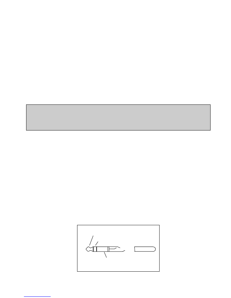
per input), connect only the Tip (hot or +) and Sleeve (ground). DO NOT connect the Ring (-). Furthermore,
DO NOT use 2 circuit phone plugs (Tip and Sleeve only). These phone plugs will short a portion of the
driver amp to ground causing damage to the driver.
Tip = Plus (+)
Ring = Minus (-)
Sleeve = Shield
Fig. 4.8
- 12 -
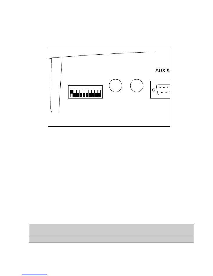
Located on the rear of the console is an array of 10 DIP switches, corresponding to the 10 inputs of Blue 5c.
Monitor muting is enabled for the given input by placing the respective DIP switch in the ON position. When
the input is active and the cooresponding channel is ON, the monitors will be muted. This is commonly
called, “Input Followed Muting”.
1
ON
2 3 4 5 6 7 8 9 10
MONITOR
MUTING
L
R
OUTPUTS
1
14
Monitor level is controlled by a fader located on the right side of the unit.
4.8.1 Connecting Monitor Amplifiers
Most modern power amplifiers need only a small amount of voltage to drive them to maximum output,
which in many cases is greater than the power handling capacity of the monitor speakers. The low input
sensitivity of these amplifiers is easily exceeded by the output voltage capability of most console outputs, so
the installer is advised to consider protecting studio speakers by matching the output voltage of the console to
the input requirements of the monitor amp.
Recommended practice calls for setting control room and studio monitor amplifier gains at installation, after
which the amplifier controls are secured from tampering. The gain of the monitor amplifiers is set by
determining the maximum voltage at the console's output, with its associated level control wide open. The
gain of the monitor amplifier is set to reach maximum output (or maximum speaker power handling
capability) when this voltage is presented to its input.
This is accomplished easily when the monitor amplifier has a simple attenuator pad level control across its
input. However, most amplifiers today have a preliminary input stage before any level controls (consult your
amplifier schematics). If this is the case, full console output can overload an amplifier input causing serious
distortion and possible speaker damage. The preferred solution is to install a resistive pad at the amplifier
input to reduce the console output to the desired voltage.
!! WARNING !!
Leaving the monitor speakers active while a control room Mic is ON may
result in feedback and equipment damage.
- 13 -
4.9
Remote Start Logic System
Blue 5c provides an ‘open collector’
continuous
closure to ground for each input. Interfacing to these
contact points will vary depending upon the equipment to be remotely started. Contact LPB customer service
for tech hints and ideas. You may also find them on our www.blue5c.com website.
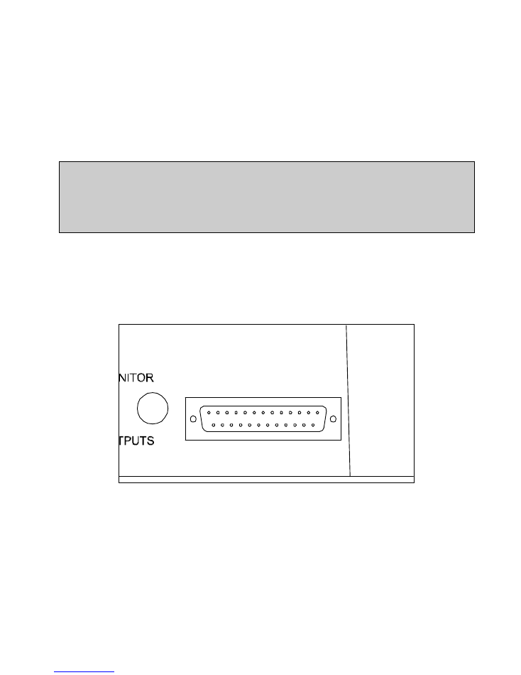
Located of the rear of the console is a 25 pin ‘D’ connector. A label on the back of this manual indicates the
function of each of these pins. Referring to figure 4.9, the 10 pins labeled ‘Tally 1’ thru ‘Tally 10’ are the
open collector that corresponds to the associated input. ‘Tally 1’ corresponds to Input 1, Tally 2 Input 2 and
so on. When the Input and the associated channel ‘ON’ button is active, the associated Tally pin will be at
ground potential until either the Input is un-selected or the Channel is turned ‘OFF’.
!! WARNING !!
Do Not connect 120vac directly to any pin on this connector. Severe damage
to the console will result and possible electric shock hazard. Switching of
large AC voltages should only be done thru external relays capable of
handling the voltage and current.
The remote start pins are as follows:
Tally 1 (Input 1) = pin 11
Tally 6 (Input 6) = pin 21
Tally 2 (Input 2) = pin 10
Tally 7 (Input 7) = pin 7
Tally 3 (Input 3) = pin 9
Tally 8 (Input 8) = pin 20
Tally 4 (Input 4) = pin 22
Tally 9 (Input 9) = pin 6
Tally 5 (Input 5) = pin 8
Tally 10 (Input 10) = pin 19
AUX & LOGIC OUTPUTS
R
1
13
14
25
Fig. 4.9
4.9.1 On Air Light
A unique feature of The Blue 5c is the built in “ON AIR” indicator. It will come on whenever the monitors
are muted. Setting and muting the monitors is explained in section 4.8 In addition, an ‘ON AIR’ tally appears
on pin 3 of the 25 pin “D” connector located on the rear of the unit. Like the other tally pins, this is an ‘open
collector’ which, when active, will be at ground potential and continuous until the channel is turned off.
This tally is typically used to drive a low-voltage DC activated solid state relay. The positive (+) pin of the
relay coil should be connected to +5VDC (located on pin 18 of the 25 pin “D” connector). The negative (-)
pin of the relay coil is connected to the ON AIR TALLY (pin 3). This approach will allow the relay to
become active when the selected input and corresponding channel are on (mute activated: see section 4.8). A
120 VAC On-Air light is connected to the relay contacts thus isloating the AC from the internal components

- 14 -
of the console. DC loads of no more than +5vdc / 100 mA should be connected to the On-Air logic output,
and a suppression diode should be connected across the relay coil.
!! WARNING !!
Do Not connect 120vac directly to any pin on this connector. Severe damage
to the console will result and possible electric shock hazard. Switching of
large AC voltages should only be done thru external relays capable of
handling the voltage and current.
5.0 Telephone Inputs and Mix Minus
Blue 5c offers a mono telephone Send bus, in addition to the Program and Cue outputs. This unit interfaces
with commercial phone hybrid systems and provides a “Mix Minus Return” to the telephone hybrid.
You may insert the Line audio from the hybrid into any of the 10 inputs.
The audio you wish sent back to the hybrid (return), should have the “SEND” button depressed above the
mixer position. This will send a Mono feed from the Program bus back to the hybrid.