Full Text Searchable PDF User Manual
Sliding Gate Operator
User's Manual
WARNING
THIS PRODUCT MUST
BE INSTALLED BY A
QUALIFIED ELECTRICIAN

BMG Imports
Sliding Gate Opener
MODEL No. LW550
Power rating: 220-240v AC 50Hz 550w
Duty Close: 0-120 adjustable Max. 30s open
Max. gate weight 1500kg
Motor rotational speed 1400rpm
Output rotational speed 46.6r/min
Approval No. SAA121472
45° C ~+ 55° C IP44 Made In China
Important Safety information
Sliding Gate Motor - Model 550 AC Sliding
This item must be installed by a qualified electrician
All safety instructions and insallation methods should be read and completely
understood by the installer and the owner prior to the installation of the gate
opener system. This product is designed and manufactured for the use indicated in
this document. Remember that all automatic gates are intended for vehicular gates
only. A separate gate or entrance must be installed for pedestrian use. Any other use,
not expressly indicated may damage the product or be a source of danger. Do not use
it on large sized gates that have a steep incline. Wrong selection of motor will result in
unreliable operation.
Owner should observe the following:
1. Do not cross the gate while it is operating
2. Keep children away from the gate and the remote control
3. Do no adjust the setting of the control panel unless you understand what you are
doing
4. Learn the use of the the emergency override key. This is crucial in the event that
the system does not work.
Installer should observe the following:
1. Make sure the gate weight does not exceed the maximum weight specified
2. The gate design must be suitable for the installation of the gate opener system
3. Ensure that the gate is installed on flat,level ground and can move and slide freely
in both directions along the entire gate length
4. Gate opener must be installed in the area where it is not easily damaged
5. Do not change with parts or components not supplied by the manufacturer
6. Make sure all wiring works are correct in accordance with electrical bylaws and in
good condition before supplying the mains power to the control panel
7. Turn OFF the power when doing any maintenance
8. Ensure the control panel box is free from water leakage and insects to avoid short
circuiting of the control panel and voiding warranty
9. Never supply mains power directly to the DC motor if cover is damaged
10. Do not install the operating system if in doubt. Contact the manufacturer or your
local agent
1/1
1
Install “Physical Gate Stops
Physical gate stops MUST be installed at each end of your gate. If the
magnetic switch on the motor fails to stop the gate cycle, the gate stops will
prevent the gate from falling off the guide rollers and causing possible injury or
damage.
Installing Motor
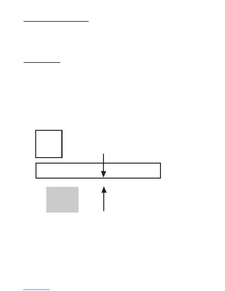
Preparation of the concrete ground surface (base) for motor mounting
Make sure that the ground surface for the motor installation is solid and level.
A good base is paramount to the proper operation of the gate opener
system. If installing cables, place these 300mm from your wall/post and
approx. 220mm in from the corner of the wall/post. The motor mounting plate
is 170mm deep x 270mm wide. Position the motor mounting plate (
side nearest to the gate) approx. 150-160mm from the wall/post and approx.
50mm in from the post driveway corner point.
Post
Gate
Motor
50mm
170mm
270mm
60mm
Top View Base Footprint
Cables from the control panel to the motor can be
per-embedded
in the base
should concealed wiring be preferred. Check with you
r
electrician. You may
have to space the bottom of the base plate with spacers to gain some height
to run wires and cables. Again check with your electrician.
Prepare for motor cable. Optional
devices
such as wired keypad, photo
beams etc. use telecom cable, cat-5 or cat-6
2/1
1

NOTE: You may need to raise the motor to allow the gear rack to fasten
properly to your gate bottom rail, so check this first by placing a piece of gear
rack on top of the motors cog alongside the gate.
Open/close the gate to ensure no fasteners are obstructing the rack.
There are 3 typical ways to fasten the motor to your concrete.
Option 1: If your gate is manufactured with 100 x 50mm rectangular bottom
rail such as the BMGI low profile model and sits about 40mm off the ground
with the wheels, you can bolt the motor directly to the concrete.
Hint: Option 2 and 3 are good for raising the motor to allow cables to be
installed freely under the motor so you do not need to be too accurate with
your cable location.
Option 2: If your gate is fitted with the standard wheel that raises the gate to
approx. 50mm from the ground you can use high mounting blocks to lift the
motor. Position these spacers under the left and right sides of the motor and
fasten to concrete.
Option 3: new concrete pad. If your gate is above 50mm off the ground you
can use the mounting plate supplied with the motor and the 4 threaded rods,
1 in each corner to act as pylons. The rods can be pressed into your concrete
pad. You can now line up the mounting plate. Once the concrete pad has
dried, you can now assemble, starting with the motor, washers and fasten
together with 4 more nuts.
Installing the gear rack to the gate:
For your gate to function smoothly you will need to install the gear rack
correctly. The outcome is to have a 2mm gap between your
gear wheel
and
the valley of the gear rack throughout the length of the gate. Temporarily
raise the motor by another 2mm using bolt-washer spacers under the motor
mounting bolts.
3/1
1
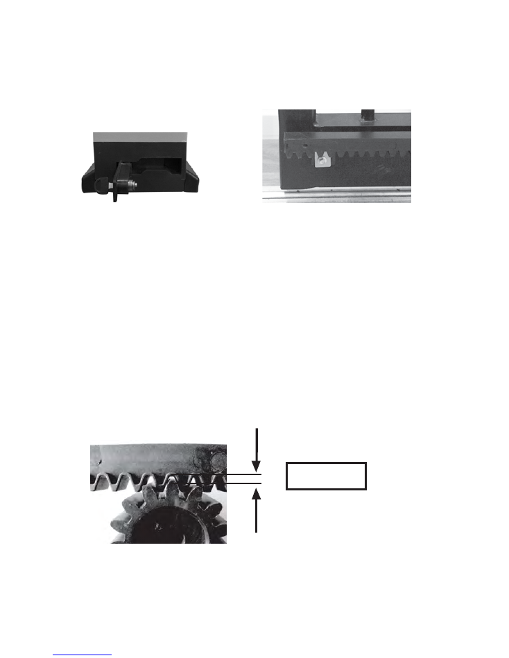
Release the auto gate to emergency release so that the gear wheel rotates
freely for the alignment and installation of the gear-rack. (see picture below)
Starting with your gate in the open position, align your first section of racking to
sit flush with the start of your gate. (See picture below)
Emergency Release
Rack installation start
Rest the first gear-rack on the gear wheel, ensure that the gear rack is level
and secure the gear-rack onto the gate using the fastenings provided. Move
the gate 1m and repeat as above until all gear-rack has been installed. Do
not fasten where
w
heels may be contacted as this will increase gate moving
resistance dramatically.
We strongly recommend you leave your gear rack over hanging (approx.
100mm) until after you have fitted your “magnet brackets” and only then cut off
any extra with a steel hacksaw. The gear rack has a steel rod inserted in the
nylon casting for strength.
Remove the washer/spacer from the motor and the gap of 2mm between the
gear wheel and the gear-rack is automatically achieved. Check to ensure
consistent meshing between the gear-rack with the gear wheel over the entire
length of the gate. Loosen the scre
w
on the gear-rack to adjust the position of
the gear rack if necessary.
2mm gap
Important Note: Gear wheel and gear rackings life depends almost
entirely on their correct meshsing
4/1
1
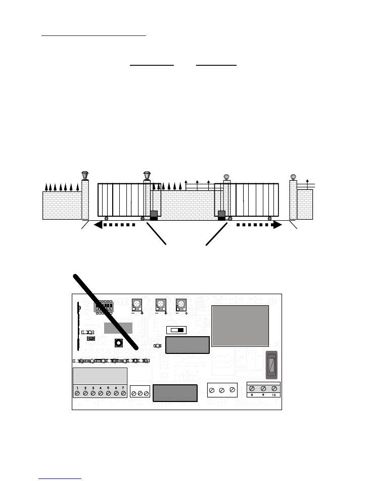
Install “Magnetic Brackets”
One magnet bracket MUST be installed at each end of your gate, attached to
your rack. Supplied is a high bracket and a low bracket, when installed they
are designed to trigger the internal magnetic limit switch. This will stop the
gate cycle BEFORE making contact with the physical gate stops.
The best way to install the ‘magnetic brackets’ is to close the gate to hit the
stop, slide back open 50mm, now slide the
LOW
magnet bracket along the
racking
until
you see
‘L
6
’
light up on the main control board, then adjust
magnet on bracket and secure. To install
HIGH
magnet, open gate full and
pull back 50mm, now slide the
HIGH
magnet bracket along the racking till
you see
‘L
7
’
light up on the main control board, then adjust magnet on
bracket and secure.
Check that both fully open and fully closed ‘magnetic brackets’ are in place on
the gear rack and are functioning correctly. Check both fully open and fully
closed physical stops are securely in place.
Closing
direction
Closing
direction
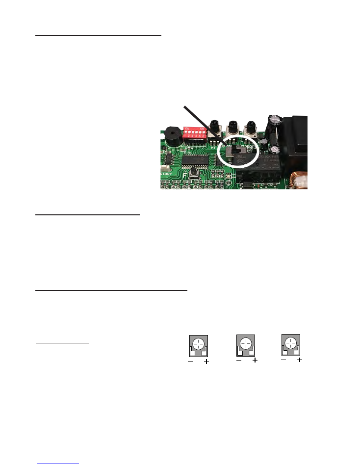
K3
L1 L2
L3
L4 L5 L6 L7
LED9
LED8
F
FORCE TORQUE
STUDY
wireless receiver
SLOW THRUST
HIGH
magnet
end
HIGH
magnet
end
LOW
magnet
end
L6 & L7 LEDs
5/1
1
Program Gate ‘Opening Direction’
When setting the motor direction switch, standing at the motor, if you
r
gate
opens to the left ‘direction switch’ should be over to the left and if the gate
opens to the right then the ‘direction switch’ should be over to the right.
To
make sure this is correct, open gate half way and lock clutch in, press
remote button and the gate should open fully.
To learn the gate slow down
Motor direction switch
6/1
1
FORCE
TORQUE
SLOW THRUST
SLOW THRUST: Adjust motor's thrust after the gate is installed.
FORCE: Rebound resistance function,
Turn clockwise to increase force to
desired setting
TORQUE: Adjust motor's power (clockwise is bigger)
Have the gate in the closed position and lock in clutch (give the gate a push
to make sure the clutch is locked). Push dip switches 4 and 6 on/up on the
control board. Press and hold
F
button on the control board for 5 seconds,
then let go. The gate will now open fully and hit the gate stop, then within a
couple of seconds will automatically close. Once the gate has closed, push
dip switch 6 off/down. Slow down no
w
completed
Test the gate opener is working correctly
If the gate loads up on your physical stops this will affect the reliability of the
gate operation. If this happens, you may need to adjust the magnet brackets.
Adjust Torque
Study
Button
Tuning remotes
Control board
Tuning remotes (remotes may already be tuned in - test first)
P
ress the Study button (left hand side of the board)
for 2 seconds
until the red
LED light goes solid and release. On your remote press the top left hand
button twice.
You will hear a beep and t
he red light on the control board will
go off to confirm tuning of remote. Now do the remaining remotes. Be car
e
ful
not to hold the Study button down too long as this will erase/wipe all remotes
tuned.
Note: only 30 remotes will tune into the on board receiver
Erase all remotes
Hold the Study button down for 5 seconds, now all remotes will be erased
Remote
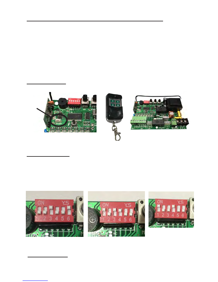
To learn auto close
On the control board, push dip switch 3
& 6
on/up
(see figure 1), all others
down
. You will be required to press the F button to set the auto close time.
Each time you press the F button you will hear a beep. Each beep will equal
1 second. Leave dip switch 3 up/on for auto close
and put dip switch 6 down.
Put 1 & 4 dip switches on/up (see figure 2).
7/1
1
Cancel auto close
Push dip switch 3 off/down
(see figure 3
).
Figure 2
Figure1
Figure 3
Additional Devices
First insert your wires in the correct location as per the labels. Check the
running of the gate each time you install a new device. This is so you do not
burn out
the system
accidentally
.
Connecting Exit Push Button:
Using speaker wire
Terminals 2 and 4 to activate open/stop/close
Connecting Keypad:
Using telecom wire
Keypad COM direct to gate open board terminal COM (#2)
Keypad NO direct to gate opener board terminal ONE (#4)
Keypad +12v direct to gate opener board
+15v
(#1)
Keypad -GND direct to gate opener board
COM
(#2)
Connecting the IR beams:
Using telecom wire
Important Note:
Terminals for eye beams are found in the bottom left corner
of the main control board. To install IR beams you will need power to both
IR beams. Connect one IR beam to the other IR beam -1 to -1 and +2 to +2.
Now connect the other IR beam direct to the main control board.
Connect -1 to -2 COM, +2 to +1 15v,
4
to 2 COM and
5
to 3 FSW
Make sure to remove the loop wire
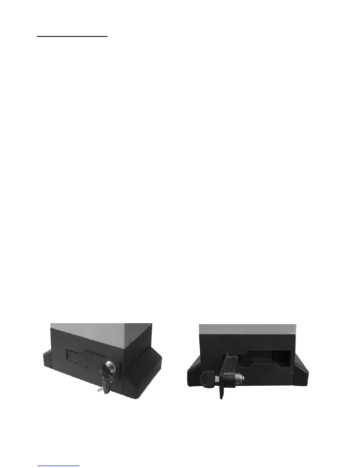
Drive release mechanism:
The motor is
equipped
with a lockable release mechanism to enable the gate
to be operated manually due to a power cut. The release
mechanism is shown below with the clutch disengaging the link between the
cog wheel and rack. Insert your key into the lock and pull the clutch outwards.
Drive release mechanism and key
Clutch disengaged
8/1
1

Troubleshooting
Number
Trouble
Cause
Method
1
Motor can’t work
*No power supply
*Blown fuse
*Capacitor decay
*Surpass load
*Effected by the thermal
protection
*Check power supply
*Change fuse
*Check if any debris on
track.
*Restart after 20min.
2
Can open (close)
But can’t close (open)
*Position of the magnet
isn’t correct
*Magnet is damaged
*Eye beams if fitted
*Adjust the position
*Change the magnet
*Re adjust magetic steel
position
*Check eyebeams are
functioning if fitted
3
Can’t locate
accurately
*Distance of the magnetic
bracket
*Internal Magnet is
damaged
*Adjust position of magnet
bracket
*Change internal magnet
4
Clutch can’t work
*Operating handle is
broken
*Clutch is jammed
*Change handle
*Manually push the gate
to lock in
5
Remote/s will not
work
*No signal
*Check there is an LED
light on the remote when
the button is pressed. If
not replace battery
*Re tune remote
6
Motor can turn but
can’t work
*Compression spring off
clutch is bad.
*Clutch is released
*Change the spring
*Close the clutch
*Adjust racking
7
Motor is humming but
gate does not go
*Capacitor damaged
* Replace Capacitor
9/1
1

Maintenance work
The drive mechanics are maintenance free. Check at regular intervals that the gate
hardware and the drive are all firmly in place. Disengage the drive and check gate
functionality. Only an easy running gate will work well with a drive.
A drive is no substitute for a poorly functioning gate.
Warranty
1.
12 months warranty from date of purchase, warranty does not cover incorrect
installation or damage by fusion and other insects.
2.
Warranty replacement and repairs are back to base.
3.
You can view our full terms of conditions at www.bmgi.com.au
4. Must be installed with a surge protector to protect the main control board from
power surges. Warranty will be voided as power surges are not covered
under warranty.
10/1
1
1.
Remote control single three key functions.
2.
Half-open function (non standard).
3.
Automatic closing function.
4.Soft stop function.
5.Full power to start.
6.
Programmable State.
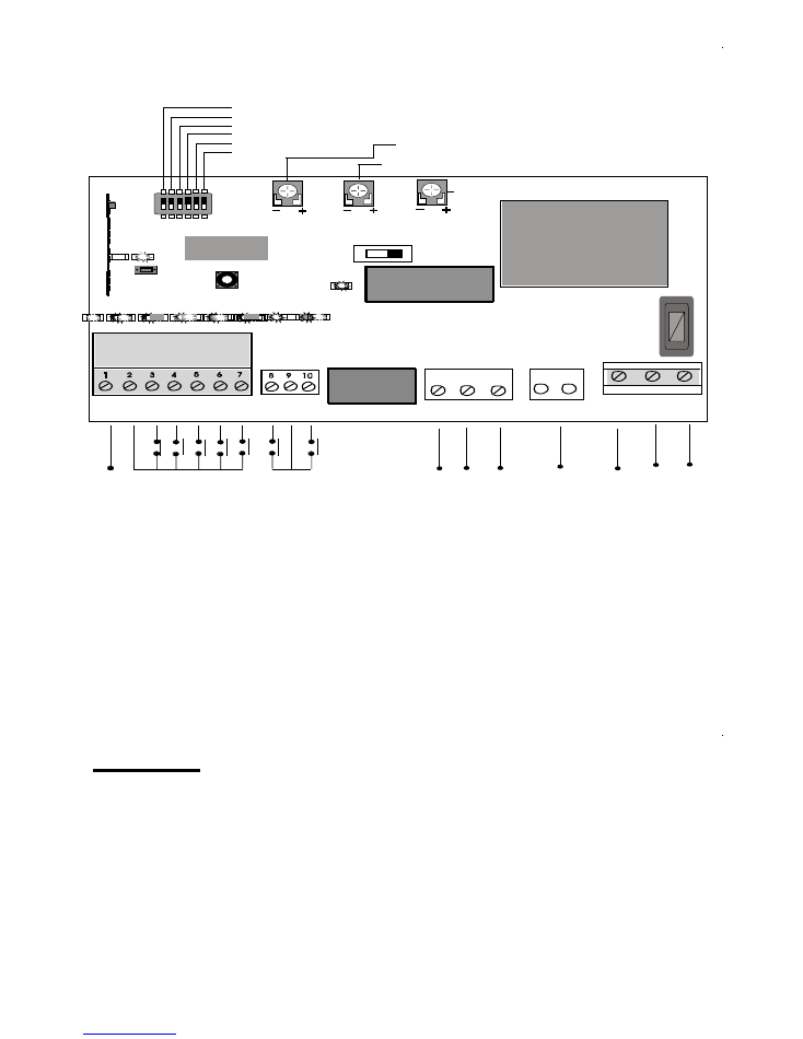
K3
L1
L2
L3
L4
L5
L6
L7
LED9
LED8
F
FORCE
TORQUE
MOTOR
N
L
AC220V
L1
COM
L2
+15V COM FSW ONE STP CL OP
C.L COM O.P
Wiring diagram
wireless receiver
Rebound resistance function,turn to max. force (clockwise)
to cancel this function.
ON
Function key
Learning key
Motor direction
Limit swicth
Adjust motor's thrust after the gate is installed.
(clockwise is bigger)
Limist switch input terminal(Closing direction)
Common terminal
Limist switch input terminal(Open direction)
15
V
10
0m
A
ma
x.
Power output
Common terminal
Infrared safety electric eye (Closing direction) input terminal
A single key circulation
Stop
input
Close input
Open input
Motor phase line
Motor common line
Motor phase line
220V AV 60W flashing lamp output.
220V Power supply
(null line)
220V Power supply
(live line)
SLOW THRUST
Adjust motor's power.(clockwise is bigger)
1
1
/1
1
I
---
Light
11
12
13
14 15
16
17 18
Earth
IMPORTANT
240 Volt power supply must be safely secured inside
the motor housing to prevent the power supply from
being disconnected from the main board. If not
secured correctly this may cause the LW550 to
become an electrical hazard.