Full Text Searchable PDF User Manual

Proteus-R
Rack-mount rate/standards/aspect ratio converter
Operation manual
(v1.00bxx)

1
Table Of Contents
Introduction .......................................................................................... 2
Video Gain Adjustment ............................................................................. 4
Chroma Gain Adjustment........................................................................... 4
Black Level Adjustment ............................................................................ 5
Audio Level Controls ................................................................................ 5
Audio Delay Control ................................................................................. 6
Tracking Delay
....................................................................................................................... 6
Genlock Controls..................................................................................... 7
Storing and Recalling Presets...................................................................... 9
Selecting Audio Sources ............................................................................ 9
Selecting Test Patterns ............................................................................11
Aspect Ratio Conversion Controls................................................................12
Preset mode
........................................................................................................................ 12
Variable mode
..................................................................................................................... 12
Border
.................................................................................................................................. 13
Disabling the ARC
................................................................................................................ 13
Appendix A...........................................................................................14
Proteus Menu Structure
...................................................................................................... 14
Appendix B ...........................................................................................22
AES Break-out cable pin ordering
..................................................................................... 22
Appendix C...........................................................................................23
Analogue Audio I/O Break-out cable pin ordering
.......................................................... 23
Please note the following regarding this manual.
Note1: throughout the text, buttons and controls are indicated by
bold red text
, and display
information in “quotation marks”.
Note 2: If you have any comments or questions, contact information is available on our website
http://www.brickhousevideo.com.
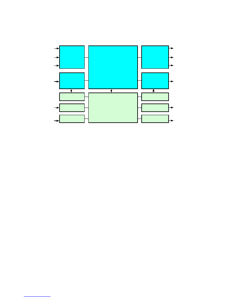
2
Analog
Video
Decoder
& ADC
SDI Input
Interface
Audio Demux
AES Input
Analog Input
AES Audio
Analog Audio
(optional)
Analog
Composite
SDI
270Mb/sec
YC
YUV
4-line/4-field
Motion-adaptive
Standards converter
Audio Synchroniser,
Block Delay,
Proc amp and Mixer
AES Audio
Analog Audio
(optional)
Analog
Video
Encoder
& DAC
SDI Output
Interface
Audio Mux
AES Output
Analog Output
Analog
Composite
SDI
270Mb/sec
YC
YUV/RGB
(rackmount
version only)
Proteus
Inputs
Outputs
Fig.1 Proteus Standards Converter Block Diagram
Introduction
The Proteus is a 4-line 4 field motion adaptive standards converter that accepts video
in any current TV standards with automatic audio synchronisation to prevent the build-
up of lip-sync errors. An extremely flexible and versatile system architecture means
that Proteus can also be used as a synchroniser and/or a format converter.
Most standards conversion processes require several fields of video delay meaning that
the audio must be delayed to compensate for this. Proteus accommodates this
compensation by providing audio delay of up to 10 seconds, which means upstream lip-
sync issues can also be solved. Such large audio delay requirements are becoming
commonplace as more and more programming is processed through digital codecs.
For video, both Analogue (composite, YC, YUV) and digital (SDI) sources are accepted,
whilst for audio, sources may be selected from the embedded audio in the input SDI
stream or alternatively AES audio or analogue audio. (Please note that for analogue
audio I/O, the appropriate option must be fitted—please contact your dealer for
details).
Proteus is able to synchronise all outputs to a genlock reference.
3
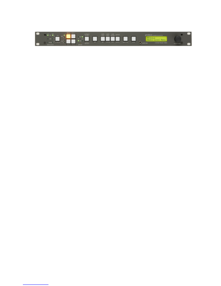
Front Panel Overview
Input Select Buttons
Proteus has 8 video inputs: 2 SDI, 2 Composite Video, 1 YUV and 1 YC (S-VHS) input.
These can be selected via the front panel 4 input select buttons on the left. The
button of the selected input is lit to indicate it has been selected. A faulty or non-
existent input is indicated by the button LED flashing. The 4 LEDs on the left of the
input select buttons, indicate whether SDI1, SD2 or CV1, CV2 is selected. Note that the
YC input is not available on early units.
Input Line Standard LEDs
The 2 Input Line Standard LEDs to the right of the input select buttons indicate the
line standard of the selected video input.
Output Line Standard LEDs
The 2 green LEDs to the right of the 2 Input Line Standard LEDs indicate the selected
line standard of the output signal. If the line standards of the input and output signals
are opposite then Proteus is in standards conversion mode. If they are the same then
Proteus enters synchroniser mode.
Genlock LED
The yellow LED is the genlock indicator. This is lit if a reference is present and flashes
if there is a reference present but it does not conform to the output line standard. If
there is no reference present, the genlock LED remains unlit.
Menu Select Buttons
To the right of the output standard button are the 5 menu select buttons,
shift
,
gain
,
chroma
,
black
and
presets
. Together with the
menu/exit
and
enter
buttons, these
buttons navigate the extensive menu structure of Proteus. When the
menu/exit
button is lit, the
rotary encoder
and
enter
key allow a top-down approach to the menu
structure. When the
menu
button is unlit, the
gain, chroma, black
and
presets
buttons
allow shortcuts to the relevant parts of the menu structure. Further shortcuts are
provided by
shift
+
gain
= audio level,
shift
+
chroma
=
audio delay,
shift
+
black
= audio
shuffle, and
shift
+
menu/exit
= genlock.
The complete menu structure is provided in Appendix A.
Front Panel Lockout
Front panel lockout preventing unwanted user disturbance can be achieved by pressing
shift
+
enter
together. Pressing
shift
+
enter
again, reactivates the front panel.
The next few pages describe the shortcut operations in more detail.

4
Video Gain Adjustment
Proteus contains 2 video proc amps, one for analogue sources only, and one for digital
levels after the appropriate video source has been selected. Both of these proc amps
can be accessed via the
gain
,
chroma
and
black
buttons described here.
Ensuring the menu button is unlit, press the
gain
button. The characters “Picture
Gain” will be displayed and the menu button will light. The
rotary encoder
will now
allow cycling through the various gain options available.
These are as follows: -
“Picture Gain”
“Y Gain”
“CV Dec Gain”
Once the desired gain adjustment is selected, press
enter
. The display will now
indicate the current setting which can be adjusted via the
rotary encoder
. Once the
desired setting has been reached, pressing the
enter
button will retain the value. If
you wish to cancel the adjustment and return to the previous setting, then the
menu/exit
button should be pressed.
Chroma Gain Adjustment
Ensuring the
menu
button is unlit, press the
chroma
button. The characters “Chroma
Gain” will be displayed and the menu button will light. The
rotary encoder
will now
allow cycling through the various chroma gain options available.
These are as follows: -
“Chroma Gain”
“Cb Gain”
“Cr Gain”
“CV Chroma Gain”
“NTSC Hue”
Once the desired adjustment is selected, press the
enter
button. The display will now
indicate the current setting which can be adjusted via the
rotary encoder
. Once the
desired setting has been reached, pressing the
enter
button will retain the value. If
you wish to cancel the adjustment and return to the previous setting, then the
menu/exit
button should be pressed.

5
Black Level Adjustment
Ensuring the menu button is unlit, press the
black
button. The characters “Picture
Gain” will be displayed and the menu button will light. The
rotary encoder
will now
allow cycling through the various gain options available.
“Y Black Level”
“Cb Black Level”
“Cr Black Level”
“CV Dec Black”
“NTSC IP Ped”
“NTSC OP Ped”
Once the desired black level adjustment is selected, press
enter
. The display will now
indicate the current setting which can be adjusted via the
rotary encoder
. Once the
desired setting has been reached, pressing the
enter
button will retain the value. If
you wish to cancel the adjustment and return to the previous setting, then the
menu/exit
button should be pressed.
Audio Level Controls
Note: Audio is an option and may not be fitted.
The Proteus contains an audio proc amp, which comes after the audio source selection
point. This allows for +/-12dB of audio gain to be applied on the output audio signals.
These gain changes may also be monitored via the headphone socket
on the front
panel.
Ensuring the
menu
button is unlit, press the
shift
+
gain
=
audio level
buttons.
The characters “Audio Gain” will be displayed and the
menu
button will light. The
rotary encoder
will now allow cycling through the various audio gain options available.
These are as follows: -
“Audio Gain”
(overall audio gain)
“1 L&R”
(channel 1 left and right simultaneously)
“2 L&R”
(channel 1 left and right simultaneously)
“1 Left”
(channel 1 left )
“1 Right”
(channel 1 right)
“2 Left”
(channel 2 left)
“2 Right”
(channel 2 right)
Once the desired adjustment is selected, press the
enter
button. The display will now
indicate the current setting which can be adjusted either via the
rotary encoder
. Once
the desired setting has been reached, pressing the
enter
button will retain the value.
If you wish to cancel the adjustment and return to the previous setting, then the
menu/exit
button should be pressed.

6
Audio Delay Control
Note: Audio is an option and may not be fitted.
Proteus contains an audio delay, which comes after the audio source selection point.
All selected audio channels are delayed equally. Depending on the standards
conversion mode, various options are available.
Tracking Delay
When the input line standard and output line standard are the same, Proteus enters
synchronisation mode. Normal synchronisation action will give occasional video frame
drops or repeats as the input video frame rate slides through the output video frame
rate (which is normally locked to reference). In this case it is appropriate to enable
tracking delay since the video delay will vary from 0ms to 33ms/40ms for 525/625 line
systems. This will give discernible lip-sync errors if the audio does not track these
delays. It is important to note that additional block delay can be superimposed on this
tracking delay to accommodate further upstream audio/video misalignments.
Fixed Delay
When the input line standard and output line standard are different, Proteus enters
standards conversion mode. The standards conversion process gives a fixed processing
delay of 33ms/40ms for 525/625 line systems (this delay refers to the input line
standard). In this case it is appropriate to enable fixed delay mode and to dial up the
appropriate delay according to the input line standard. Additional block delay can also
be added to further accommodate upstream audio/video misalignments.
Jumping or Ramping to Target Delay
When a new delay is selected, there will inevitably be a small disturbance to the audio
signal if the system ‘jumps’ to this new target delay. To alleviate this, Proteus
incorporates a ‘ramp’ option that permits the target delay to be reached over a
number of seconds. The compromise is that during the ramping time, lip-sync will be
misaligned. Note that ramping is not available for the extended audio option.
Minimum Delay
Please note that the minimum audio delay through the unit is 5ms.
Ensuring the
menu
button is extinguished, press the
shift
+
chroma
buttons. The
characters “Block Delay Adj” will be displayed and the
menu
button will now light.
The
rotary encoder
will now allow cycling through the various audio delay options
available. These are as follows: -
“Block delay Adj” (overall audio block delay adjust 0-320mS)
“Track Delay Mode”
(option to track to video delay in synchroniser mode)
“Block delay Response” (option to jump or ramp to the selected audio delay)

7
Once the desired adjustment is selected, press the
enter
button. For the first
selection (“Block delay Adj”), the display will now indicate the current setting which
can be adjusted via the
rotary encoder
. Once the desired setting has been reached,
pressing the
enter
button will retain the value. If you wish to cancel the adjustment
and return to the previous setting, then the
menu/exit
button should be pressed.
For the last 2 selections (“Track Delay Mode” and “Block delay Response”), there is a
choice. This can be selected with the
rotary encoder
. The state surrounded by
chevrons is considered to be the active state.
Genlock Controls
Ensuring the
menu
button is extinguished, press the
shift
+
black
. The characters “H
Fine Phase” will be displayed and the
menu
button will now light.
The
rotary encoder
will now allow cycling through the various genlock options
available.
These are as follows: -
“H Fine Phase”
(in ns)
“H Coarse Phase”
(in samples)
“V Phase”
(in lines)
“Free Run Frequency”
“Action On Losing Input”
“Action On Losing Genlock”
Once the desired adjustment is selected, press the
enter
button.
For the first 4 selections (“H Fine Phase”, “H Coarse Phase”, “V Phase” and “Free Run
Frequency”), the display will indicate the current setting, which can be adjusted via
the
rotary encoder
.
Once the desired adjustment is selected, press the
enter
button. The display will now
indicate the current setting which can be adjusted either via the
rotary encoder
. Once
the desired setting has been reached, pressing the
enter
button will retain the value.
If you wish to cancel the adjustment and return to the previous setting, then the
menu/exit
button should be pressed.

8
Genlock Controls (continued)
For the last 2 selections (“Action On Losing Input” and “Action On Losing Genlock”),
there is a choice. This can be toggled by using the
rotary encoder
and
enter
buttons.
The state surrounded by chevrons is considered to be the active state.
Adjusting the free run frequency
Proteus contains an internal VCXO that controls all of its output timing. This VCXO can
either be locked to the genlock signal or it can free-run. As a precaution, the free-run
frequency can be adjusted to a value close to that of the existing genlock signal. This
is so that if the genlock fails for whatever reason, the disturbance to the output is
minimised whilst the problem is fixed.
To adjust the free run frequency, perform the following list of operations: -
1) Ensure that the “Action on losing Genlock” setting is selected as “free run”.
2) Connect one of the composite output signals to one channel of either a waveform
monitor or oscilloscope.
3) Connect the genlock signal to the other channel of the waveform monitor or
oscilloscope.
4) Ensure the output line standard is the same as that of the genlock signal.
5) Select “Free Run Frequency” from the Genlock Controls Menu (see previous page).
6) The display will now indicate the Free Run Frequency as a percentage. 50% is the
default setting with adjustment from 25% to 75%.
The Free Run Frequency can be adjusted via the
rotary encoder
. This should be
adjusted such that the run-through frequency of the two signals on the waveform
monitor or oscilloscope is brought to zero.
Once the desired setting has been reached, pressing the
enter
button will retain the
value. If you wish to cancel the adjustment and return to the previous setting, then
the
menu/exit
button should be pressed.
Note: The setting will be retained even when Proteus is switched off.

9
Storing and Recalling Presets
Ensuring the
menu
button is unlit, press the
shift
+
menu
=
presets
buttons. The
characters “Presets Menu” will be displayed and the
menu
button will now light. The
rotary encoder
will now allow cycling through the various gain options available.
These are as follows: -
“Factory Default”
“Recall 1”
“Recall 2”
“Store 1”
“Store 2”
Once the desired preset selection is selected, press the
enter
button. The display will
now ask for confirmation. Either press
enter
again to carry out the desired preset
option or press the
menu/exit
button to escape to the top level of the presets menu.
Note that if the “Factory Default” option is used and then the “store 1” and “store 2”
presets activated, the unit’s parameters will be returned to the original state
installed at the factory.
Selecting Audio Sources
Note: Audio is an option and may not be fitted.
The output audio is simultaneously available on the AES and analogue outputs as well
as being embedded in the video SDI stream. The input audio can be selected from
either embedded audio from the selected SDI input, the AES input or the analogue
audio inputs. Alternatively a mixture of sources is also possible.
It should be noted that audio sources that are asynchronous both to the SDI video
source and to each other can be accommodated. The one exception to this is that the
2 embedded audio channels within the selected audio group must be synchronous to
each other. In practice this is usually the case anyway.
The quickest way to select the audio sources is via the button on the extreme left-
hand side of the panel. This allows the user to switch between Embedded, AES and
Analogue inputs. The input sources can also be split between channels 1&2 and 3&4.
Holding down the
Shift
button while pressing the audio source selector will cycle
channels 3 and 4 only through the input source options.
(cont. next page)

10
Audio Menu access
Ensuring the
menu
button is extinguished, press the
menu
button. The characters
“Proteus ARC Menu” will be displayed. The
rotary encoder
will now allow cycling
through the various top level options available These are as follows: -
“ARC Menu”
“Aud Source Menu”
“Video Gain Menu”
“Chroma Menu”
“Black Level Menu”
“Audio Level Menu”
“Audio Delay Menu”
“Genlock Menu”
“Presets Menu”
“Extended Menus”
“Status”
Select “Audio Source Menu” and press the
enter
button. The
rotary encoder
buttons
will now allow cycling through the second level options available.
These are as follows: -
“Embedded”
“AES”
“Analogue”
“X-Point”
The state with the chevrons around it is considered to be the active state. If it is
desired to mix the audio sources, then select “X-point” using the
rotary encoder
and
press
enter
.
Level 3 and Level 4 options will now allow for mixed source selection of the audio
outputs. (See the menu table in Appendix A). In selecting the audio channels, it is
best to start with selecting the digital source as either embedded, AES or a mixture of
both. This is because the digital selection must be done in stereo pairs to ensure
correct audio synchronisation with video. Once the digital selection has been made,
then the output audio channels can be made from any combination of digital and audio
signals.

11
Selecting Test Patterns
A selection of test patterns can be switched onto the output of both the analogue
video signals and independently also the digital video signals (SDI). This is useful for
testing downstream equipment or monitors. It can also be useful for testing
downstream cable links.
To select the test patterns navigate to the “Test Pattern Select” menu, under the
“Extended Menus”, section.
As well as a video test pattern the embedded SDI output test patterns also contain an
embedded audio test pattern with channel ident. This is an extended tone followed
by a short tone in channel 1, 2 short tones in channel 2, 3 short tones in channel 3 and
4 short tones in channel 4.
It should be noted that audio test patterns on the AES outputs is not currently
supported.

12
Aspect Ratio Conversion Controls
Note: Aspect Ratio Conversion (ARC) is an option and may not be fitted.
There are two ways to control ARC – preset mode and variable mode. The ARC can
also be turned off.
Preset mode
There are 8 preset conversions:
“4:3 => 4:3 Pillar Box”
“4:3 => 14:9 Pillar Box”
“4:3 => 16:9 Middle Cut”
“4:3 => 16:9 Anamorphic”
“16:9 => 4:3 Centre Cut”
“16:9 => 4:3 Anamorphic”
“16:9 => 14:9 Letter Box”
“16:9 => 16:9 Letter Box”
The first four are valid for 525-line input and 625-line output. They convert a 4:3 full-
screen image on 4:3 input screen onto a 16:9 output screen. The last four are valid for
625-line input and 525-line output. They convert a 16:9 full-screen image on a 16:9
input screen onto a 4:3 output screen.
To select the preset conversions navigate to the “Preset” menu, under the “Aspect
Ratio Conversion” menu. When “Preset” menu is selected, Proteus works in preset
mode until “Variable” menu or “Off” is selected.
Variable mode
Variable mode allows direct control of the output picture position and size both
vertically and horizontally, therefore any conversion may be set up.
Variable vertical and horizontal size and position are represented in percentage units.
For size, 0% means no resizing. 50% expands the picture to 150% of its normal size. A
positive percentage is a size increase and a negative percentage is a size decrease. For
position, 0% positions the image centred on the output. 50% moves the image half way
off-screen. A positive percentage moves the image down and to the right and a
negative percentage moves the image up and to the left.
When “Zoom” is turned on, both vertical size and horizontal size can be changed
together if one of them is adjusted. When “Zoom” is turned off, vertical size and
horizontal size can be adjusted separately.
To select “Zoom”, “Horizontal Size”, “Vertical Size”, “Horizontal Position” or
“Vertical Position”, navigate to the “Variable” menu, under the “Aspect Ratio
Conversion” menu. When “Variable” menu is selected, Proteus works in variable mode
until “Preset” menu or “Off” is selected.
Once “Horizontal Size”, “Vertical Size”, “Horizontal Position” or “Vertical Position” is
selected by pressing the enter button, follow the steps below.
The display will now indicate the current setting which can be adjusted via the
rotary
encoder
.

13
Once the desired adjustment is selected, press the
enter
button. The display will now
indicate the current setting which can be adjusted either via the
rotary encoder
. Once
the desired setting has been reached, pressing the
enter
button will retain the value.
If you wish to cancel the adjustment and return to the previous setting, then the
menu/exit
button should be pressed.
Border
Border colour can be selected from eight colours. Both vertical and horizontal border
edges can also be trimmed on a line-by-line and/or pixel-by-pixel basis. When the ARC
is turned off, the border adjustments are also turned off.
To adjust the border, navigate to the “Border” menu, under the “Aspect Ratio
Conversion” menu. “Horizontal Trim” and “Vertical Trim” can be controlled in the
same way as “Horizontal Size”.
Disabling the ARC
Picture resizing can be turned off by selecting “Off” under the “Aspect Ratio
Conversion” menu. When it is turned off, the output picture position and size are set
to 0% and the border is turned off.

14
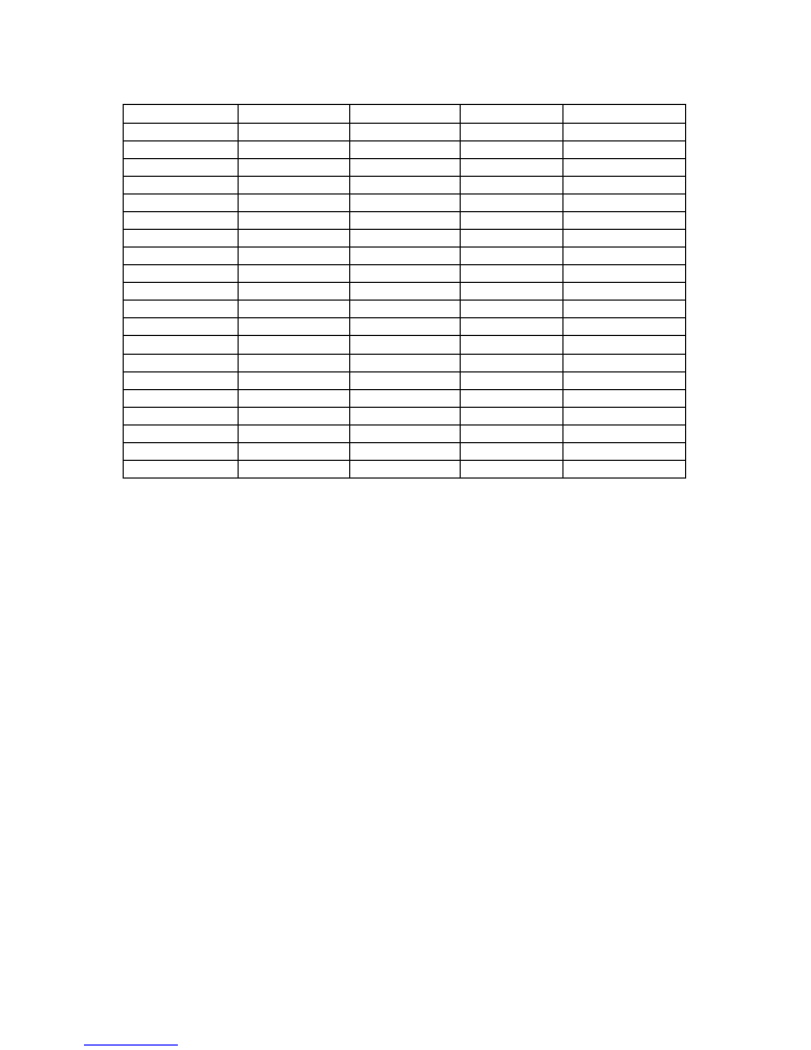
Appendix A
Proteus Menu Structure
Note: Some menus may not function or may not be present dependent on options installed.
Top level
Level 2
Level 3
Level 4
Level 5
ARC Menu
Preset
4:3 => 4:3 PB
4:3 => 14:9 PB
4:3 => 16:9 MC
4:3 => 16:9 Ana
16:9 => 4:3 CC
16:9 => 4:3 Ana
16:9 => 14:9 LB
16:9 => 16:9 LB
Variable
Zoom
On
Off
Horizontal Size
8888
Vertical Size
8888
Horizontal Position
8888
Vertical Position
8888
Border
Colour
Black
Dark Grey
Grey
Light Grey
White
Green
Red
Blue
Horizontal Trim
8888
Vertical Trim
8888
Off

15
Top level
Level 2
Level 3
Level 4
Level 5
Aud Source Menu
Embedded
AES
Analog
X-Point
Left Ch - Audio Pair1
Digital Audio Channel 1
Digital Audio Channel 2
Digital Audio Channel 3
Digital Audio Channel 4
Analogue Audio Channel 1
Analogue Audio Channel 2
Audio Analogue Channel 3
Analogue Audio Channel 4
Right Ch - Audio Pair1
Digital Audio Channel 1
Digital Audio Channel 2
Digital Audio Channel 3
Digital Audio Channel 4
Analogue Audio Channel 1
Analogue Audio Channel 2
Analogue Audio Channel 3
Analogue Audio Channel 4
Left Ch - Audio Pair2
Digital Audio Channel 1
Digital Audio Channel 2
Digital Audio Channel 3
Digital Audio Channel 4
Analogue Audio Channel 1
Analogue Audio Channel 2
Analogue Audio Channel 3
Analogue Audio Channel 4
Right Ch - Audio Pair2
Digital Audio Channel 1
Digital Audio Channel 2
Digital Audio Channel 3
Digital Audio Channel 4
Analogue Audio Channel 1
Analogue Audio Channel 2
Analogue Audio Channel 3
Analogue Audio Channel 4
Digital Audio Channel 1/2 Embedded Audio Pair 1
Embedded Audio Pair 2
AES1
AES2
Digital Audio Channel 3/4 Embedded Audio Pair 1
Embedded Audio Pair 2
AES1
AES2

16
Top level
Level 2
Level 3
Level 4
Level 5
Video Gain Menu
Picture Gain
+0.00dB
Y Gain
+0.00dB
CV Dec Gain
1
Chroma Menu
Chroma Gain
+0.00dB
Cb Gain
+0.00dB
Cr Gain
+0.00dB
CV Chroma Gain
1
NTSC Hue
0deg
Black Level Menu
Y Black Level
+0.00mV
Cb Black Level
+0.00mV
Cr Black Level
+0.00mV
CV Dec Black
+0.00mV
NTSC IP Ped
Ped On
Ped Off
NTSC OP Ped
Ped On
Ped Off
Audio Level Menu Audio Gain
+0.00dB
Pair 1 L&R
+0.00dB
Pair 2 L&R
+0.00dB
Pair 1 Left
+0.00dB
Pair 1 Right
+0.00dB
Pair 2 Left
+0.00dB
Pair 2 Right
+0.00dB

17
Top level
Level 2
Level 3
Level 4
Level 5
Audio Delay Menu Block Delay Adj
0ms
Track Delay Mode
Track
Fixed
Blk Delay Response
Ramp
Jump
Extended Delay Adj
0ms
Genlock Menu
H Fine Phase
100ns
H Coarse Phase
0 Samples
V Phase
0 Lines
Free Run Freq
50%
Action on No Ip
Cut to Black
Freeze
Action on No Glk
Lock to Ip
Free Run
Presets Menu
Factory Default
Enter to Confirm
Recall 1
Enter to Confirm
Recall 2
Enter to Confirm
Store 1
Enter to Confirm
Store 2
Enter to Confirm

18
Top level
Level 2
Level 3
Level 4
Level 5
Level 6
Extended Menus Audio Controls
Audio Ip Control Embedded Aud Grp
Group1
Group2
Group3
Group4
Audio Op Control Embedded Aud On/Off On
Off
Embedded Aud Pack
Smpte 272M
Every Line
Monitor Select
Ch 1/2
Ch 3/4
Phase Reverse
Aud 1 Right Rvs
Enable
Disable
Audio 2 Right Rvs Enable
Disable
Ana Vid Ip Setup Force Standard
NTSC
PAL-I
PAL-M
PAL-cN
NTSC 4.43
SECAM
AUTO

19
Top level
Level 2
Level 3
Level 4
Level 5
Ana Vid Op Setup
Chroma On/Off
Chroma On
Chroma Off
Burst On/Off
Burst On
Burst Off
Active Pic Width
Narrow Blank
Wide Blank
Assign Standard
NTSC-M
PAL-I
PAL-M
PAL-cN
Std Conversion
Motion Apt Setup
On
Off
Motion Thr Setup
Mode
Auto
Manual
Motion Threshold
(no action)
Video TPG
Test Pattern Sel
100% Col Bar
75% Col Bar
Multiburst
SDI Matrix
100%Bar+Mbst
SDI Op TPG OnOff
Off
On
Ana Op TPG On/Off Off
On
20
Top level
Level 2
Level 3
Level 4
Level 5
Engineering menu PCB Issue
1
Firmware Ver
2.1
Software Ver
2.2
Checksum 1
FFFFFFFF
Checksum 2
FFFFFFFF
Serial number
1xxxx
Speed Grade
6
Options Code
FFFFFFFF
Option Settings
Mnemonic Setting :Shr
Long
Scroll Speed
Very Slow
Slow
Medium
Fast
Disp Brightness
(no action)

21
Top level
Level 2
Level 3
Level 4
Level 5
Status
SDI Ip Status
Locked
625 Lines
Analog Ip Status
Unlocked
NTSC
Genlock
Missing
NTSC
Unlocked
Embedded Audio
Present
Checksum OK
Em Audio Ch1
Linear
Present
Em Audio Ch2
Linear
Present
AES1 Status
Present
No Errors
Linear
AES2 Status
Present
No Errors
Linear
Audio Delay
5ms

22
Appendix B
AES Break-out cable pin ordering
Note: AES audio is an option and may not be fitted.
The AES I/O can be accessed via the 15-way D-type at the rear of Proteus
The Pin out is as follows: -
Pin 1
AES_IN1+
Pin 9
AES_OUT
1
+
Pin 2
GND
Pin 10
GND
Pin 3
AES_IN1-
Pin 11
AES_OUT
1
-
Pin 4
GND
Pin 12
GND
Pin 5
AES_IN2+
Pin 13
AES_OUT
2
+
Pin 6
GND
Pin 14
GND
Pin 7
AES_IN2-
Pin 15
AES_OUT
2
-
Pin 8
GND

23
Appendix C
Analogue Audio I/O Break-out cable pin ordering
Note: Analogue audio is an option and may not be fitted.
The Analogue audio Inputs and outputs can be accessed via the 2x15-way D-types at the rear of Proteus
The Pin-outs are as follows: -
Inputs
Pin 1
Analogue1R_IN+
Pin 2
GND
Pin 3
Analogue1R_IN-
Pin 4
GND
Pin 5
Analogue1L_IN+
Pin 6
GND
Pin 7
Analogue1L_IN-
Pin 8
GND
Pin 9
Analogue2R_IN+
Pin 10
GND
Pin 11
Analogue2R_IN-
Pin 12
GND
Pin 13
Analogue2L_IN+
Pin 14
GND
Pin 15
Analogue2L_IN-
Outputs
Pin 1
Analogue1R_OUT+
Pin 2
GND
Pin 3
Analogue1R_ OUT-
Pin 4
GND
Pin 5
Analogue1L_ OUT+
Pin 6
GND
Pin 7
Analogue1L_ OUT-
Pin 8
GND
Pin 9
Analogue2R_ OUT+
Pin 10
GND
Pin 11
Analogue2R_ OUT-
Pin 12
GND
Pin 13
Analogue2L_ OUT+
Pin 14
GND
Pin 15
Analogue2L_ OUT-