Full Text Searchable PDF User Manual

ENGLISH
RAM T1 & T2
Marine Linear Actuator
User Manual
bandg.com
simrad-yachting.com

2
The information in this manual was, to the best of our knowledge,
correct when it went to press and Simrad or B&G cannot be liable for
any inaccuracies or omissions. There may also be differences
between the specifications in the manual and the product as a result
of ongoing development for which we accept no liability.
This precision engineered product was designed and manufactured in
the United Kingdom.
Please keep this manual in a safe place

3
CONTENTS
Important Safety Information
Compliance Statement
Emergency Quick Release
Emergency
Steering
Description
Performance
• Technical
Data
Dimensions
Actuator Selection
Location
Tiller bolt
Mounting Foot
Quadrant
Considerations
Coil Connections
Maintenance
Servicing
Fault finding
Hydraulic Fluid
Commissioning
Dismounting the unit from its base
Dimensions for Mounting Foot
General Information
Contact Details
End of Life Disposal
Page 4
5
6
7
8
9
10
11
12
13
15
16
17
18
19

4
IMPORTANT SAFETY INFORMATION
Failure to install and maintain this equipment in accordance with the
instructions contained in this Manual could result in damage or injury.
This equipment must be installed and maintained by a person who is
qualified to do so. This equipment is only for use with marine autopilots
within the limitations stated in the following pages. Autopilot steering
systems are navigational aids and the user must still maintain a perma-
nent watch.
This equipment meets the latest EMC (Electromagnetic Compatibility)
standards required for use in the marine environment.
In order to ensure conformance and to prevent interference with
electronic systems the unit must be properly bonded to earth and the
supply cables screened.
Caution!
In operation this unit can rotate the vessels wheel rapidly.
Keep clear of the wheel when this unit is engaged to avoid entrapment.
Beware of hot motor and solenoid components and the risk of
entrapment from moving parts.
Do not flash test.
COMPLIANCE STATEMENT
The RAM T1 & T2 complies with CE under directive 2014/30/EU. The
relevant Declaration of Conformity is available in the following websites
under model documentation section:
www.simrad-yachting.com or www.bandg.com
Complies with the requirements of level 2 devices of the Radio
communications (Electromagnetic Compatibility) standard 2017.
Warning!
The user is cautioned that any changes or modifications not expressly
approved by the party responsible for compliance could void the user’s
authority to operate the equipment.
5
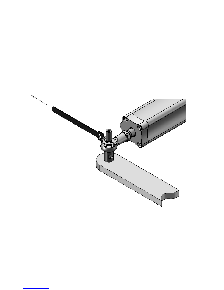
EMERGENCY QUICK RELEASE
In the unlikely event of failure of the actuator a quick release R-Clip is fitted
to the tiller bolt which secures the actuator to the steering quadrant.
Pull the red tab to release the R-Clip and then manually lift the actuator
clear of the steering quadrant.
EMERGENCY STEERING - PRIMARY STEERING FAILURE
If the primary steering fails it may be possible to steer the boat via the
autopilot controls.

6
DESCRIPTION
The RAM T1/T2 Hydraulic linear actuator combines a cylinder, pump,
motor, clutch and reservoir in a pre-filled, sealed unit. Designed to be
used on vessels fitted with mechanical primary steering that can be back
driven.
When the clutch is disengaged the cylinder is free and moves with the
primary steering. To operate the unit in autopilot mode the course com-
puter energises the clutch solenoid coil and runs the bi-directional motor
to extend and retract the ram.
Internal relief valves protect the unit and its mountings from rudder
strikes, grounding etc.
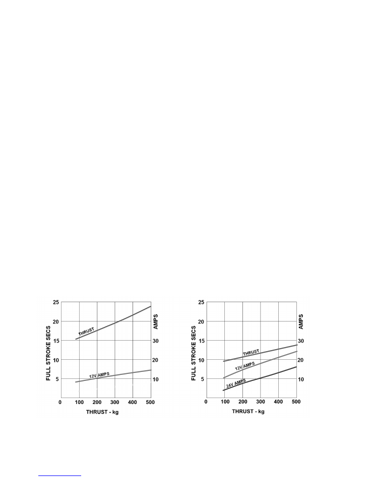
PERFORMANCE
Hard over time
Typical max thrust
seconds at 5 kg
kg
RAM
T1
13
700
RAM T2
9
700

7
TECHNICAL DATA
Voltage
T1 = 12 VDC, T2 = 12 / 24 VDC
Current
Typical
Amp-hour
Typical Current
60 kg at 25% duty
Intermittent 650 kg
12v
24v
12v
24v
RAM T1
2.0
-
19.0
-
RAM
T2
2.5
1.3
25.0
12.0
Ingress protection
IP67
EMC Protection
BS EN 60945:2002 (DC)
Ignition Protection
BS EN 28846:1993
Declaration of
Conformity EMC
Directive
2014/30/EU
Ambient operating
Temperature
-15 to + 55 deg C
Max Operating
Thrust
700
kg
(Intermittent)
Relief Valve setting
62 bar
(730 kg)
Orientation
Red lead to positive - Extends
Black lead to positive – Retracts
Clutch coil
12 watt
Clutch connection
DIN 43650 (6-8 mm cable)
Fluid
ISO VG10 to VG40 hydraulic mineral fluid
to
ISO
6743-4
HV
The following commercial fluids are suitable.
Fuchs Renolin B 15 HV1
Seastar
HA5430
Weight
8
kg
8
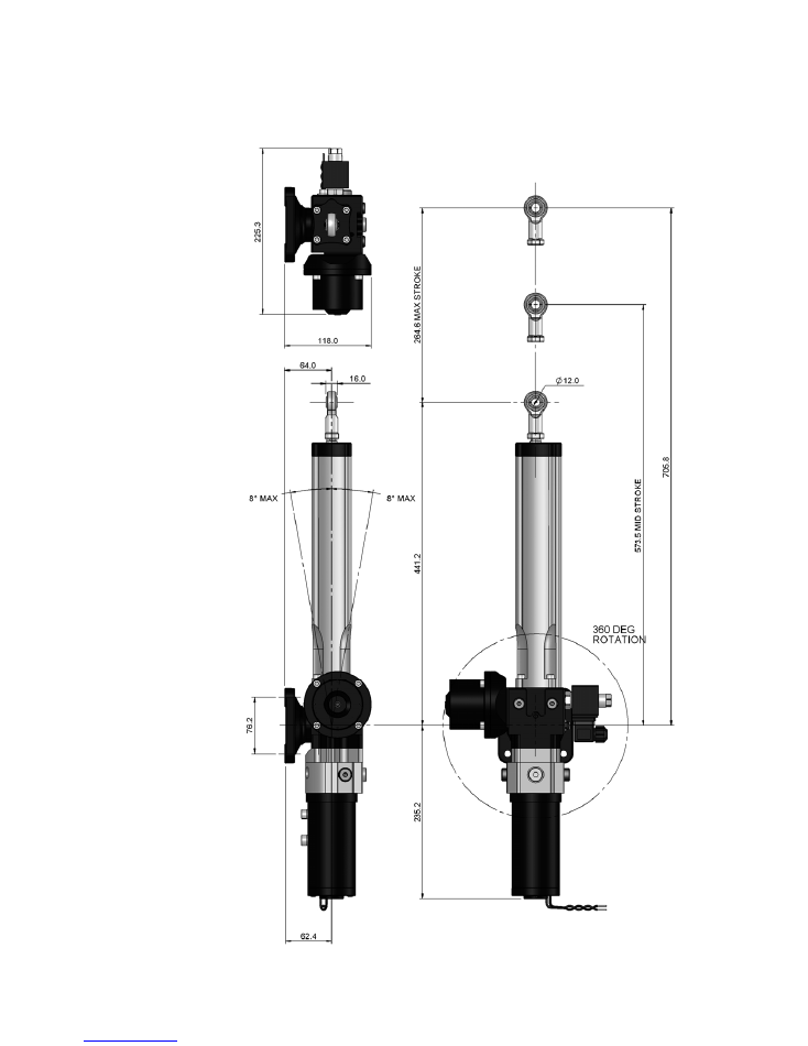
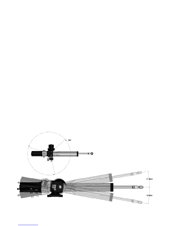
DIMENSIONS
9
ACTUATOR SELECTION
It is important to select the correct size of actuator as it directly influences the
steering performance and power consumption.
The type of vessel to be steered must be considered. The hard over time may
be faster on a light weight planning craft and modern yachts or slower on a
displacement power boat or long keel yacht.
Also consider the rudder, an unbalanced rudder will require more torque than
a semi-balanced or balanced design.
Hard over time
Tiller arm Rudder Deg. Typical Max Torque
RAM
T1
13
sec
190
mm
80
120
kg
13
sec
213
mm
70
140
kg
13
sec
245
mm
60
160
kg
RAM
T2
9
sec
190
mm
80
120
kg
9
sec
213
mm
70
140
kg
9
sec
245
mm
60
160
kg
Hard over time is the time to move the cylinder full stroke (255 mm at 5 kg)
Typical max torque intermittent is calculated at 650 kg thrust.
RAM
T1
25°C
RAM
T2
25°C
10
LOCATION
The RAM T1 & T2 Actuators are designed for under-deck installations only.
When considering where to mount the actuator the following points should
be taken into account.
: Keep cable runs short
: Mount away from sources of heat
: Install the actuator above areas liable to flooding.
: Use a solid surface, capable of supporting the large thrusts generated by
this unit.
: Ensure that piston movement is limited by the rudder hard stops and not
by the actuator end stops.
: Allow sufficient clearance for removal of the mounting pin. (See page 17)
: Check that no part of the actuator fouls the vessel or rudder quadrant
throughout its full range of movement.
: Keep the area in which it is mounted clear of equipment and obstructions.
: Maintain access to the quick release tab at all times and ensure that it is
not liable to entanglement.
11
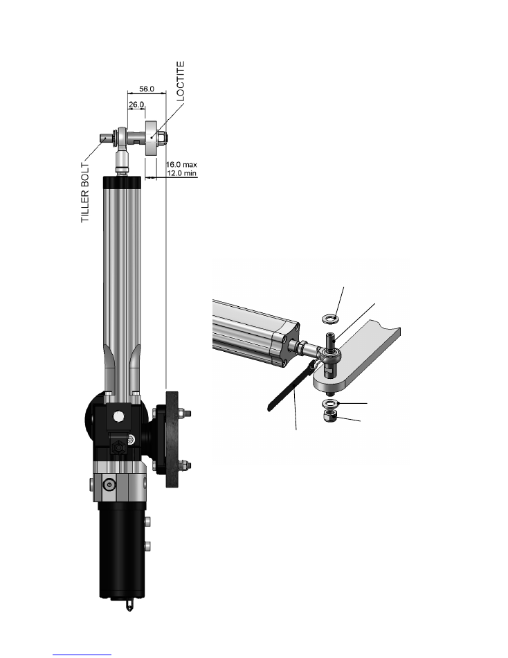
TILLER BOLT
The tiller bolt supplied is suitable for
a quadrant thickness of 12 to 16 mm.
The tiller bolt mounting hole should
be drilled Ø12.2 to 12.3 mm.
An application of Loctite 638 or
equivalent where shown is
recommended.
Tighten the M12 nut to 27 Nm Torque
MOUNTING FOOT
The four M8 nuts, bolts and washers
supplied are suitable for mounting the
actuator onto a surface of
between 12 mm and 24 mm thick.
Tighten the four M8 nuts to 17 Nm.
WASHER
TILLER BOLT
WASHER
M12 LOCK NUT
R-CLIP & QUICK
RELEASE TAB
12
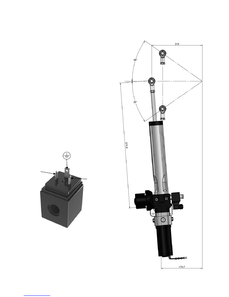
QUADRANT
Typical installation for an 8.4”
(213 mm) radius with total
rudder angle of 70 degrees.
CONSIDERATIONS
Allow sufficient clearance for removal
of the mounting pin (Ref. page 17)
and rod end from the tiller bolt.
COIL CONNECTIONS
PIN 1
POSITIVE
PIN 2
NEGATIVE
NOT USED

13
MAINTAINANCE
The RAM T1/T2 is a sealed unit, quality precision engineering will ensure
many years of trouble free service if the following points are adhered to.
: Keep the piston rod free from damage
: Avoid exposing the unit to salt water.
Perform the following checks regularly:
: Check the security of the mounting bolts and tiller pin.
: Examine electrical cables and connections for damage and corrosion.
: Lubricate the mounting pin and rod end with marine grade grease.
SERVICING
In the unlikely event that new seals are required a kit is available:
Hydraulic Projects Ltd Part No. ML+40sk.
Please quote your units serial number when ordering (Ref. page 19).
Caution
For filling and bleeding a special tool is required:
Hydraulic Projects Ltd Part no. R4051.
Failure to use this tool may result in damage to the actuator.

14
The motor is a non-serviceable item and should be replaced with a new
motor and drive coupling Kit.
Part Nos. 12V UNITS = R4510-sk 12 100 X
24V UNITS = R4510-sk 24 100 X
Quote your units serial number when ordering Ref. page 19)..
The motor can be replaced without affecting the integrity of the hydraulic
circuit.
To remove the motor:
Undo the two M6 socket head cap screws and remove the motor, coupling
and water seal O ring.
If the coupling is worn or damaged replace. Lubricate the slots with a small
quantity of good quality grease.
If any hydraulic fluid is found in the coupling area the shaft seal must be
replaced – see service kit ML+40sk for instructions.
Reassemble by replacing the O ring, engage the coupling between the
motor and pump shafts, ensure the motor locates correctly in the pump
spigot.
Using low strength thread locking compound, replace and tighten the two
M6 socket head cap screws. (13.5 Nm).
Caution
Keep all parts clean during dismantling and reassembly.

15
FAULT FINDING
Under no circumstances dismantle the unit unless it is certain that
the fault is internal. Doing so will allow air into the cylinder,
requiring the unit to be bled for which special tools are needed.
Ref. page 13.
Caution
Any damage to the piston rod will damage its seals and allow air into the
cylinder and oil leaks.
1) Motor does not run
: check electrical connections.
: check course computer output.
2) Motor runs, but erratic or no piston movement
: check for solenoid operation.
: check for air in the cylinder and external leaks.
: check drive coupling.
3) Excessive noise
: check the motor for damage.
: check for air in the cylinder and external leaks.
: check drive coupling.
4) Failure of clutch to engage or disengage
: check solenoid operation.

16
HYDRAULIC FLUID
Caution
Do not use Brake fluid
Use mineral based good quality hydraulic fluid compatible with nitrile hy-
draulic seals.
Ref Technical Data on page
7.
COMMISSIONING
Caution
Be aware of the danger of moving linkages and the risk of entrapment.
The unit is pre-filled and sealed from new. Do not disassemble the unit,
this will allow air to enter and necessitate refilling and bleeding the unit
Ref. page 13.
Use the primary steering to check the full range of movement before com-
missioning the autopilot
Caution
Check the unit for damage and leaks after installation.

17
DISMOUNTING THE UNIT FROM ITS BASE
The RAM T1/T2
features a quick-dismount base.
To remove the base from the unit first take off the coil which is secured
by a 17 mm A/F nut. Next undo and remove the Allen screw ‘A’ and
the retaining plate ‘B’ . Withdraw the mounting pin ‘C’ which will release
the base.
NOTE!
The pin is a close engineered fit and if it proves difficult to remove take
off the plastic cap from the head of the pin and insert screw ‘A’ into it.
It will then be possible to withdraw the pin using a pair of pliers or
grips.
IMPORTANT!
Avoid damage to the pin
Assembly is a reversal of the removal process. Ensure the plastic cap
is re-fitted to the pin upon completion.
18
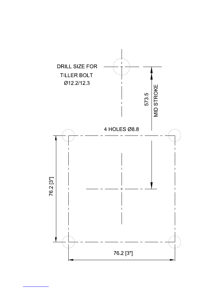
DIMENSIONS FOR MOUNTING FOOT
(NOT
TO
SCALE)

19
Keep this manual in a safe place. Quote the model and serial
numbers in all correspondence.
Model Number:
________________________________
Serial Number:
________________________________
Date of Purchase:
________________________________
Dealer:
________________________________
________________________________
________________________________
CONTACT DETAILS
For inquiries in general, contact Simrad or B&G:
www.simrad-yachting.com
or
www.bandg.com
For inquiries of spare parts, contact Hydraulic Projects Limited:
www.hypro.co.uk
GENERAL INFORMATION
END OF LIFE DISPOSAL
Please dispose of End of Life items responsibly.
In the event that you are unable to use your
nearest local authority civic amenity sites to
recycle, units can be returned to your dealer.

988-12093-001