Full Text Searchable PDF User Manual
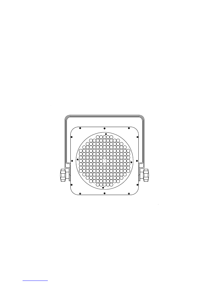

AURORAE LED PAR LP-10
This LED PAR 64 can light features with 180 Ultra Bright 10mm LED bulbs, double yokes,
DMX controllable, sound activated and 10 built-in automated programs. Aurorae LP-10
LED Slim PAR 64 can installed with internal ROM that remains the final DMX address,
running program and menu setting after power off. Users could adjust the color intensity,
RGB color mixing or run the build in programs with out any DMX controller. Great
options of operating on AC power or battery pack (Cable for the battery pack included).
With it's slim designed of only 4” thick case, made it the ideal fixture for Mobile DJ
lighting and Event Lighting.
Features
z
6 channel DMX-512 slim LED PAR can
z
RGB color mixing with or without DMX controller: Adjust intensity on each color (RGB)
from 0-100%
z
Unit can operate remotely without being connected to AC power ( use battery pack )
z
Internal memory- DMX address, setting and running programs remains after power off
z
Control panel functions: Master/Slave/DMX, sound activated, Built-in programs
z
Flicker free operation
z
Power linking up to 20 unit @ 110V
z
Double bracket as floor stand
Specifications:
•
Beam angle 25°
•
Light source: 60 red, 60 green, 60 blue LEDs
•
4 button LED display control panel
•
Control panel functions: Master/Slave/DMX, sound activated, Built-in programs
•
Lux: 1350 @ 3 meter ( Red 270, Green 460, Blue 760 )
•
3 pin XLR in/out
•
Power: 110V 60Hz 17W, AC current: 0.3A
•
AC power: Auto switching 90V-240V 50/60Hz
•
DC input: 12V 1.2A
•
Fuse: 7A
•
Weight: 5.75 lbs
•
Dimension: 8.5” x 8.5” x 4”
Ver 1.1
Page 1

Safety Instructions
z
Always connect the fixture to a circuit with a suitable electrical ground.
z
Please keep this User Manual for future consultation. If you sell the unit to another user, be sure that
they also receive this instruction booklet.
z
Always make sure that you are connecting to the proper voltage, and that the line voltage you are
connecting to is not higher than that stated on the decal or rear panel of the fixture.
z
This product is intended for indoor use only! To prevent risk of fire or shock, do not expose fixture to
rain or moisture.
z
Make sure there are no flammable materials close to the unit while operating.
z
The unit must be installed in a location with adequate ventilation, at least 20 in (50 cm) from adjacent
surfaces. Be sure that no ventilation slots are blocked.
z
Always disconnect from power source before servicing or replacing fuse and be sure to replace with
same fuse source.
z
Maximum ambient temperature (Ta) is 104° F (40° C). Do not operate fixture at temperatures higher
than this.
z
In the event of a serious operating problem, stop using the unit immediately. Never try to repair the unit
by yourself. Repairs carried out by unskilled people can lead to damage or malfunction. Please contact
Aurorae Inc for service.
z
Never connect the device to a dimmer pack.
z
Make sure the power cord is never crimped or damaged.
z
Never disconnect the power cord by pulling or tugging on the cord.
z
Never carry the fixture directly from the cord. Always use the hanging/mounting bracket.
z
Avoid direct eye exposure to the light source while it is on.
AC Power
This fixture runs on 96~240 VAC, 50/60 Hz. Before powering on the unit, make sure the line voltage to
which you are connecting it is within the range of accepted voltages.
Always connect the fixture to a switched circuit. Never connect the fixture to a rheostat (variable resistor)
or dimmer circuit, even if the rheostat or dimmer channel is used only as a 0 to 100% switch.
Mounting
z
When selecting an installation location, consider ease of access to the product for operation,
programming adjustments and routine maintenance.
z
Always mount this product making sure that there is adequate room around it for ventilation.
z
Do not expose this product to extreme temperature changes, rain, or humidity.
z
If mounting this fixture overhead, make sure that the location where you are mounting it can support its
weight.
Ver 1.1
Page 2
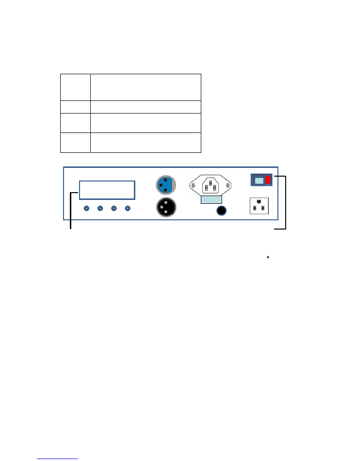
LED control panel
<MODE> Used to scroll through the current operating
mode, as well as back out of the current
menu option
<ENTER> Used to select a value and store it to memory
<UP>
Used to select increasing advancement in the
value
<DOWN> Used to select decreasing advancement in the
value
AC/DC SWITCH
Using 100~240VAC
Put AC/DC switch at AC position when using AC input
Using battery pack/ 12VDC
Caution
Disconnect all AC power cord.
Do not use power linking on AC power when connecting to the battery pack.
Once disconnected, connect the battery pack power connector (included in package) to DC outlet.
The LED fixture must be disconnected from the battery when charging the battery.
Bracket/Yoke Assembly
The lock wash goes between the black plastic knob and the bracket. The flat washer is between the
bracket and the fixture.
MODE
ENTER
UP
DOWN
AC
DC
DMX IN
DMX OUT
DC
POWE
R
AC
IN
AC OUT
LED DISPLAY
AC/DC SWITCH
FUSE
MODE
ENTER
UP
DOWN
AC
DC
DMX IN
DMX OUT
DC POWER
INPUT
AC IN
AC OUT
LED DISPLAY
AC/DC SWITCH
FUSE
Ver 1.1
Page 3
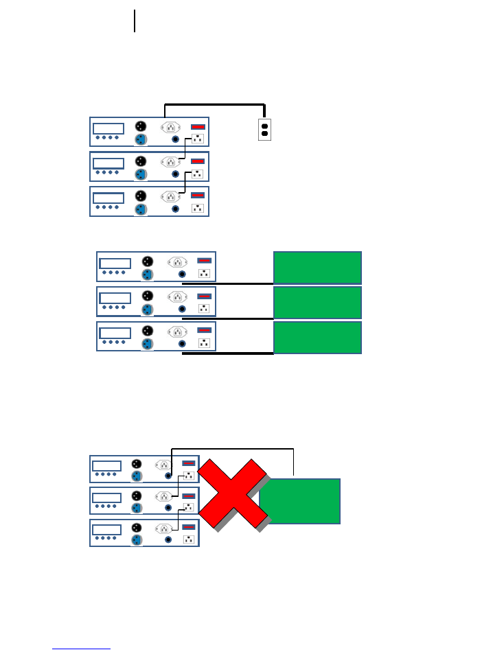
AC POWER LINKING
DC / BATTERY
A
DO NOT SETUP AS POWER LINKING WHEN USNIG BATTERY/DC
MODE
AC Power
Outlet
90V ~240V
Battery
DC
DC
DC
Battery Cable: White Stripe + ( Positive ) , Black – ( Negative )
Battery
Battery
Battery
Ver 1.1
Page 4
Fixture DMX addressing
All fixtures should be given a DMX starting address when using a DMX controller, so the correct fixture
responds to the correct control signal. This digital starting address is the channel number from which the
fixture starts to “listen” to the digital control information sent out from the DMX controller. The allocation of
this starting DMX address is achieved by setting the correct DMX address on the digital display located on
the back of the fixture.
You can set the same starting address for all fixtures or a group of fixtures, or set different address for each
individual fixture. Be advised that setting all you fixtures to the same DMX address will subsequently control
all fixtures in the same fashion, in other words, changing the settings of one channel will affect all the fixtures
simultaneously. If you set each fixture to a different DMX address, each unit will start to “listen” to the
channel number you have set, based on the quantity of control channels (DMX channels) of
each fixture. That means changing the settings of one channel will only affect the selected fixture.
AURORAE LED PAR LP-10, is a six channel fixture, you should set the starting DMX address of the first
unit to 1, the second unit to 7 (6 + 1), the third unit to 13 (6 + 7), and so on.
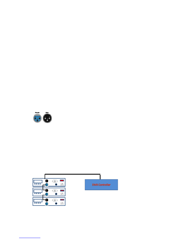
Signal Linking
In order to use this fixture in a DMX or master/slave operation, you must daisy chain, using DMX cables to link from one
fixture to another.
XLR Pin Data: 1 = Ground, 2 = Data (-), 3 = Data (+)
DMX Mode
This mode allows the unit to be controlled by any universal DMX controller. If you are unfamiliar with DMX,
1)
Press the <MODE> button until is displayed DMX address ( A001- A255 ),
2)
Use the <UP> and <DOWN> buttons to select the desired DMX address.
3)
Press the <ENTER> button to store the address.
4)
Press the <MODE> button to go back to previous Menu.
DMX
IN
DMX
OUT
DMX
IN
DMX
OUT
DMX
IN
DMX
OUT
Ver 1.1
Page 5
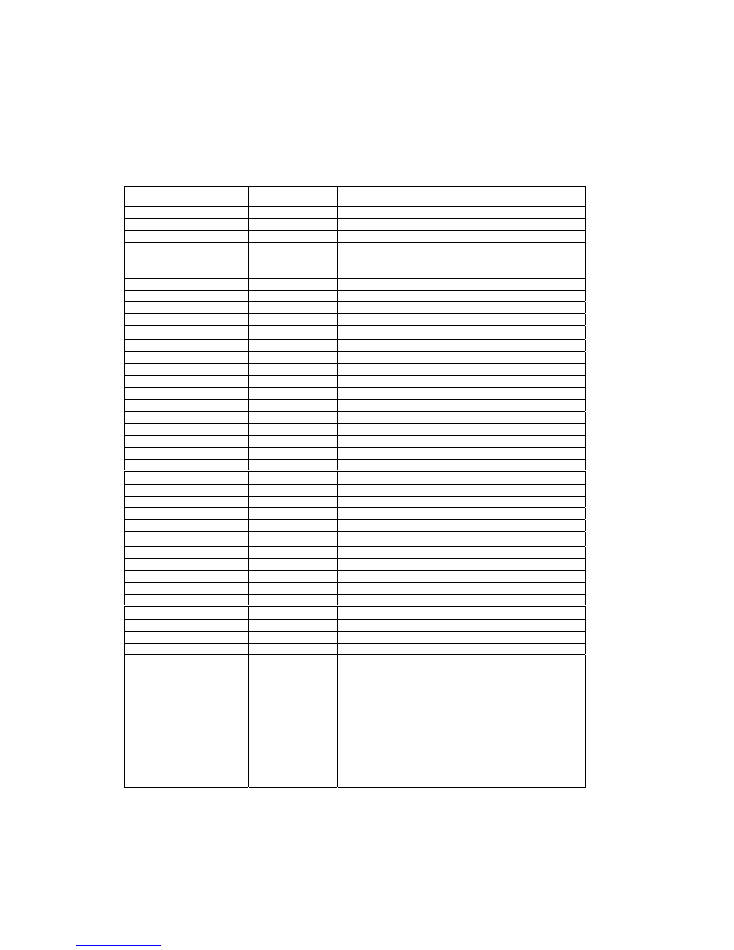
Functions and Values:
DMX CHANNEL
DMX VALUE
SPECIFICATION
CHANNEL 1 : RED
0-255
DIM : 0 – 100%
CHANNEL 2 : GREEN
0-255
DIM : 0 – 100%
CHANNEL 3 : BLUE
0-255
DIM : 0 – 100%
CHANNEL 4 : DIMMER
0 -1
0
11-17
18-255
NO FUNCTION
SHUTTER CLOSED
DIMMER: 0-100%
CHANNEL 5: MAC
RO
0
00
-
016
NO FUNCTION
017-023
BLACK OUT
024-031
RED 70% GREEN 100% BLUE 100%
032-039
RED 100% GREEN 70% BLUE 100%
040-047
RED 100% GREEN 50% BLUE 100%
048-055
RED 100% GREEN 25% BLUE 100%
056-063
RED 100% GREEN 0 BLUE 100%
064-071
RED 70% GREEN 0 BLUE 100%
072-079
RED 50% GREEN 0 BLUE 100%
080-087
RED 30% GREEN 0 BLUE 100%
088-095
RED 0 GREEN 0 BLUE 100%
096-103
RED 0 GREEN 25% BLUE 100%
104-111
RED 0 GREEN 50% BLUE 100%
112-119
RED 0 GREEN 70% BLUE 100%
120-127
RED 0 GREEN 100% BLUE 100%
128-135
RED 0 GREEN 100% BLUE 70%
136-143
RED 0 GREEN 100% BLUE 50%
144-151
RED 0 GREEN 100% BLUE 25%
152-159
RED 0 GREEN 100% BLUE 0
160-167
RED 25% GREEN 100% BLUE 0
168-175
RED 50% GREEN 100% BLUE 0
176-183
RED 70% GREEN 100% BLUE 0
184-191
RED 100% GREEN 100% BLUE 0
192-199
RED 100% GREEN 80% BLUE 0
200-207
RED 100% GREEN 60% BLUE 0
208-215
RED 100% GREEN 40% BLUE 0
216-223
RED 100% GREEN 30% BLUE 0
224-231
RED 100% GREEN 20% BLUE 0
232-239
RED 100% GREEN 10% BLUE 0
240-247
RED 100% GREEN 0 BLUE 0
248-255
RED 100% GREEN 100% BLUE 100%
CHANNEL 6 : EFFECT
0 -5
06 -35
36 -65
66 –95
96 –125
126 –155
156 –255
186--215
216--245
246--250
251--255
NO FUNCTION
STROBE SPEED
PAUSE STROBE
EFFECT COLOR FADE STROBE
COLOR CHANGING
COLOR FADE DIMM IN THAN DIMM OUT
COLOR FADE SHUTTER OPEN THAN DIMM OUT
COLOR FADE SHUTTER CLOSE THAN DIMM IN
COLER FADE RAINBOW EFFECT
SOUND ACTIVATION MODE 1
SOUND ACTIVATION MODE 2
Ver 1.1
Page 6

Stand-Alone Mode (Sound-Active, Auto Mode)
1.
This mode allows a single unit to run to the beat of the music, or the unit will auto change in Auto Mode.
Press the <MODE> button until is displayed “ SLAE “.
2.
Use the <UP> and <DOWN> buttons to locate the desired program ( FLAS, FAdE, FbdE, ACC-, Sud1,
Sud2 ).Some programs are static, and some can trigger to sound. See the Menu Values section on the
previous page for a complete list of programs.
3.
Each program has settings which can be configured by pressing <ENTER> while the program is
displayed. Press <ENTER> while the program is displayed. Use <UP> and < DOWN> buttons to the
desired setting ( Level 00 – 12 ) and press <ENTER>, Use <UP> and <DOWN> buttons to change the
level ( 00 – 12) and press <ENTER>.See the Menu Values section on the previous page for a complete
list of settings.
4.
Press the <MODE> button to go back to previous Menu.
Static Color Mixing
This function will allow the fixture to select specific colors without the use of a DMX console.
1)
Press <MODE> until <r---> displayed then press <ENTER>
2)
Use <UP> and <DOWN> buttons to select desired color Red <r--->, Green <9---> and Blue <b--->
3)
Press <ENTER>
4)
Use <UP> and <DOWN> buttons to select desired value for each color ( from 000 – off to 255 –
brightness )
5)
Press <ENTER>
6)
Press <MODE> to go back to previous page, repeat steps 2 – 5 to set another color.
Ver 1.1
Page 7
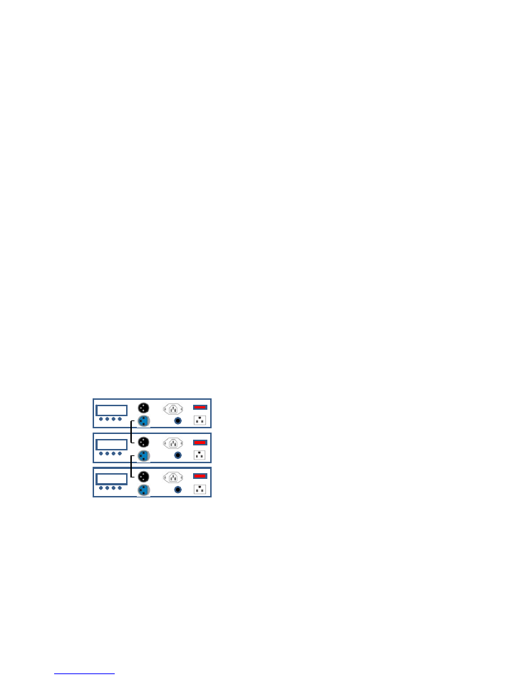
Master/Slave Mode (Master Sound, Master Auto)
The Master/Slave mode allows LP-10 fixture to control one or more LP-10 fixtures without a DMX controller.
The controlling fixture becomes the “master” when running an Auto program, a Custom program, or by being
in static mode. The controlled fixtures are the slaves and you must set them to SLAVE mode from their
respective control panels. During the Master/Slave operation, the slave fixtures will operate in unison with the
master fixture.
The master and slave fixtures link to each other using the standard DMX serial connection.
Do not connect a DMX controller to the fixtures operating in Master/Slave mode. Otherwise, the signals from
the DMX controller may interfere with the signals from the master unit.
This mode will allow you to link up to 32 units together without a controller.
1) Use standard DMX cables to daisy chain your units together via the DMX connector on the rear of the
units. For longer cable runs we suggest a terminator at the last fixture.
2) Determine which fixture will be the master. Connect a DMX cable from the DMX output connector of the
master to the DMX input connector of other fixtures.
3) Continue connecting the slaves together with DMX cables
4) Press the
<MODE>
button on the master unit, until is displayed “ SLAE “.
5) Use the
<UP>
and
<DOWN>
buttons to locate the desired program ( FLAS, FAdE, FbdE, ACC-, Sud1,
Sud2 ).
Some programs are static, and some can trigger to sound. See the Menu Values section on the previous page
for a complete list of programs.
6) Each program has settings which can be configured by pressing
<ENTER>
while the program is displayed.
Press
<ENTER>
while the program is displayed. Scroll through to the desired setting and press
<MODE>
.
See the Menu Values section on the previous page for a complete list of settings.
DC
DC
DC
DMX
IN
DMX
OUT
DMX
IN
DMX
OUT
DMX
IN
DMX
OUT
MASTER
SLAVE
SLAVE
Ver 1.1
Page 8
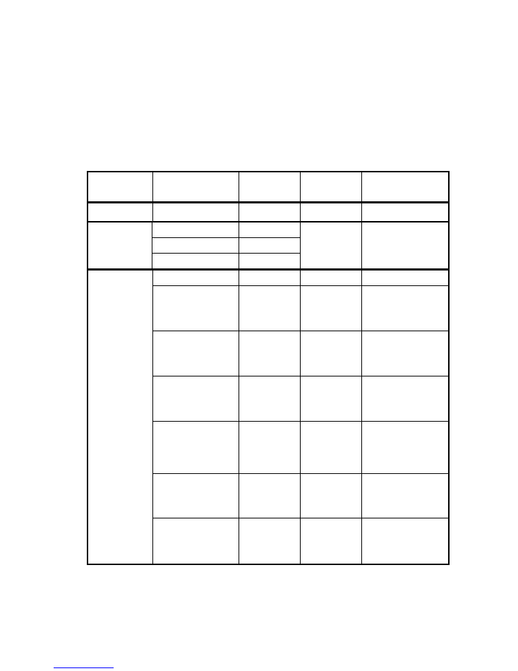
DISPLAY MENU
MAIN
MANUAL
FEUNCTION SELECTION
VALUE INSTRUCTION
A001
A001-A512
DMX ADDRESS
A001 – A512
R--- RED
G--- GREEN
RBG
B--- BLUE
0-255
0 – OFF
255 BRIGHTNESS
SLAE
SLAVE MODE
SLAVE MODE
FLAS AUTO
COLOR
FADE
( STROBE
EFFECT )
FL00 – FL12
STROBE RATE:
FL00 – LO
FL12 – HI
FADE
AUTO COLOR
FADE
FA00 – FL12
FADE TIME:
FA00 – SLOW
FA12 - FAST
FBDE
AUTO COLOR
FADE
(DIMM IN THAN
DIMM OUT )
FB00 – FB12
FADE TIME:
FA00 – SLOW
FA12 - FAST
ACC-
AUTO COLOR
CHANGING
AC00 – AC12
COLOR CHANGING
TIME:
AC00 – SLOW
AC12 - FAST
SUD1
SOUND
ACTIVATED
( STROBE
EFFECT )
SLAE
SUD2
SOUND
ACTIVATED
( COLOR
CHANGING )
Ver 1.1
Page 9

Technical Specifications
Weight & Dimensions
Length ....................................................................................................................... 8.5 in (216 mm)
Width ...........................................................................................................................8.5in (216 mm)
Height ........................................................................................................................... 4in (102mm)
Weight ........................................................................................................................3.75lbs (1.7 kg)
Power
Auto-ranging .................................................................................................. 96~240 VAC, 50/60 Hz
Power Consumption @ 120 V........................................................................................18 W (0.3 A)
Power Consumption @ 230 V........................................................................................17 W (0.568 A)
DC Input .......................................................................................................................... 12V / 1.3A
Fuse …………………………………………………………………………………………………………7A
Battery Cable: ………………………………………..… White Stripe +( Positive ) , Black - ( Negative )
Inrush Current ......................................................................................0.3 A @ 110 V, 0.2 A@ 230 V
Power Linking ...................................................................................................20 units max @ 110 V
Light Source
Type ..............................................................................................................10mm, 50,000 hrs LEDs
Configuration............................................................................180 LEDs (60 Red, 60 Green, 60 Blue)
Photometric
Beam angle:..................................................................................................;..................................25º
Luminance:............................................................................................................... 1350 Lux @ 3 m
Thermal
Maximum ambient temperature ..................................................................................... 104° F (40° C)
Control & Programming
Data input..........................................................................................................3-pin XLR male socket
Data output .................................................................................................. 3-pin XLR female socket
Data pin configuration.........................................................................Pin 1 Ground, pin 2 (-), pin 3 (+)
Protocols .....................................................................................................................USITT DMX512
DMX Channels......................................................................………………………………………….…6
Warranty Information
Warranty.......................................................................................................... 1-year limited warranty
Ver 1.1
Page 10