Full Text Searchable PDF User Manual
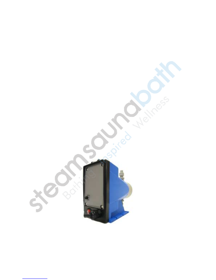
AromaMist
AromaMist
AromaMist
AromaMist
Pump
Model
AI-5
Installation and
Operation Manual
rev. 3z.9505

Page
2
AromaMist
AromaMist
AromaMist
AromaMist
Pump Model AI-5
Installation and Operation Manual
Table of Contents
I.
Introduction………………………………………………….…….
3
II.
Safety and Operating Information………………………………
3
III.
Pump Package Contents………………………………………..
4
IV.
Installation
A. Location……………………………………………………….
4
B. Mounting The Pump…………………………………………
4
C. Electrical………………………………………………………
5
D. Plumbing………………………………………………………
5
E. Control (Aroma Switch)……………………………………...
6
F. Typical Installation……………………………………………
7
G. Step By Step Installation………………………..……………
7
V.
Start-up
Priming the Pump……………………………………..…………
11
VI.
Operation Warnings………………………………………………
12
VII.
Operation………………………………………………………… 13
VIII.
Troubleshooting…………………………………………………. 14

Page
3
I. Introduction
Congratulations, you have just purchased the world’s most advanced aroma oil
metering pump, the
AromaMist
AromaMist
AromaMist
AromaMist
pump.
This instruction manual covers all facets of the installation and operation of the
AromaMist
AromaMist
AromaMist
AromaMist
pump including unpacking, mounting, electrical, plumbing, control, pump
connections, and start-up.
All information in these instructions is based on the latest product information available
at the time of publication. Accurate Industries Et Al., Inc. reserves the right to make
changes at any time without notice. Please read this manual completely before
proceeding.
Observe safety protocols and heed all warnings and precautions for safe and efficient
installation and operation of the
AromaMist
AromaMist
AromaMist
AromaMist
pump.
WARNING: It is recommended to have a certified licensed electrician
and plumber install the
AromaMist
AromaMist
AromaMist
AromaMist
pump system.
II. Safety and Operating Information
CAUTION: Please read this manual in its entirety prior to installing or
operating the
AromaMist
AromaMist
AromaMist
AromaMist
pump system.
A. Chemical Compatibility
AromaMist
AromaMist
AromaMist
AromaMist
metering pumps are designed to work with
AromaMist
AromaMist
AromaMist
AromaMist
oils only.
Failure to do so may void the warranty or pose serious health hazards.
B. Safety Equipment and Preparation
Always wear the proper protective clothing and gear when working around
chemicals and chemical metering pumps. Safety glasses, gloves, and aprons can
prevent accidental exposure to chemicals.
C. In Case of Accident
If a chemical spillage occurs, consult the Material Safety Data Sheet (MSDS) for
specific instructions regarding the chemical being used.
D. Liquids Under Pressure
Liquids under pressure can present a special hazard when a line or seal is
punctured resulting in the spraying of chemical many yards away.
E. Safe Installation
Do not install the
AromaMist
AromaMist
AromaMist
AromaMist
pump system without reading and understanding the
Operation Warning section (V) and Operation section (VII) of this manual.
Page
4
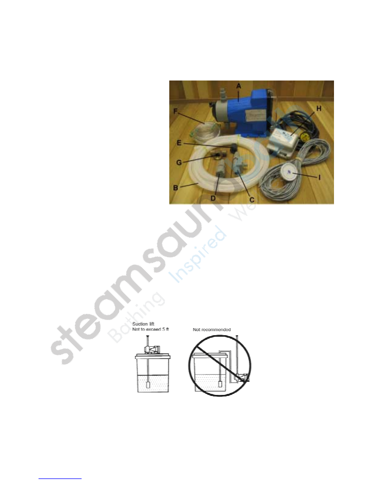
III. Pump Package Contents
AromaMist
AromaMist
AromaMist
AromaMist
Pump Package Contents
A.
AromaMist
AromaMist
AromaMist
AromaMist
Pump
B.
⅜
” Discharge/suction tubing, 20’
C.
3-function valve
D.
F
oot valve
E.
Ceramic weight
F.
⅜
” Vinyl priming tubing, 10’
G.
½” Brass T
H.
Power supply module
I.
Aroma switch
IV. Installation
A. Location
Select a pump mounting location convenient to the aroma oil supply and a source of
power for the pump. Do not install the pump in a location where the ambient
temperature exceeds 100 degrees Fahrenheit or where water can freeze. A location
that is locked or secure from children is highly recommended.
The
AromaMist
AromaMist
AromaMist
AromaMist
pump should be installed no more than five vertical feet above
aroma oil source. See Typical installation on page 7 of this manual.
B. Mounting The Pump
Secure pump with appropriate hardware (not provided) to shelf or stand using the
four (4) slots in pump base.
Page
5
C. Electrical
AromaMist
AromaMist
AromaMist
AromaMist
pump model AI-5 is a 120V AC pump and has a voltage regulated
internal power supply capable of operating in the range of approximately 95 to
135 VAC. Use a supply voltage of 100 to 120 VAC for best results. The 3-wire
grounded plug must be used with provided power supply module in a 3-wire
grounded wall outlet.
CAUTION: Never remove ground wire from plug.
CAUTION: Do not position power supply cord in direct contact
with steam line.
D. Plumbing
1. Tubing Connections
The
AromaMist
AromaMist
AromaMist
AromaMist
pump uses carefully matched components to achieve a
predictable metering output. This predictability can only be maintained if all fitting
sizes remain unaltered.
Do not
attempt to reduce tubing size. All tubing
connection should be double checked to insure against leakage.
CAUTION: Do not position tubing in direct contact with steam
line.
NOTE: When cutting lengths of tubing for your installation, ensure a
clean, square cut. Use short lengths of tubing whenever possible.
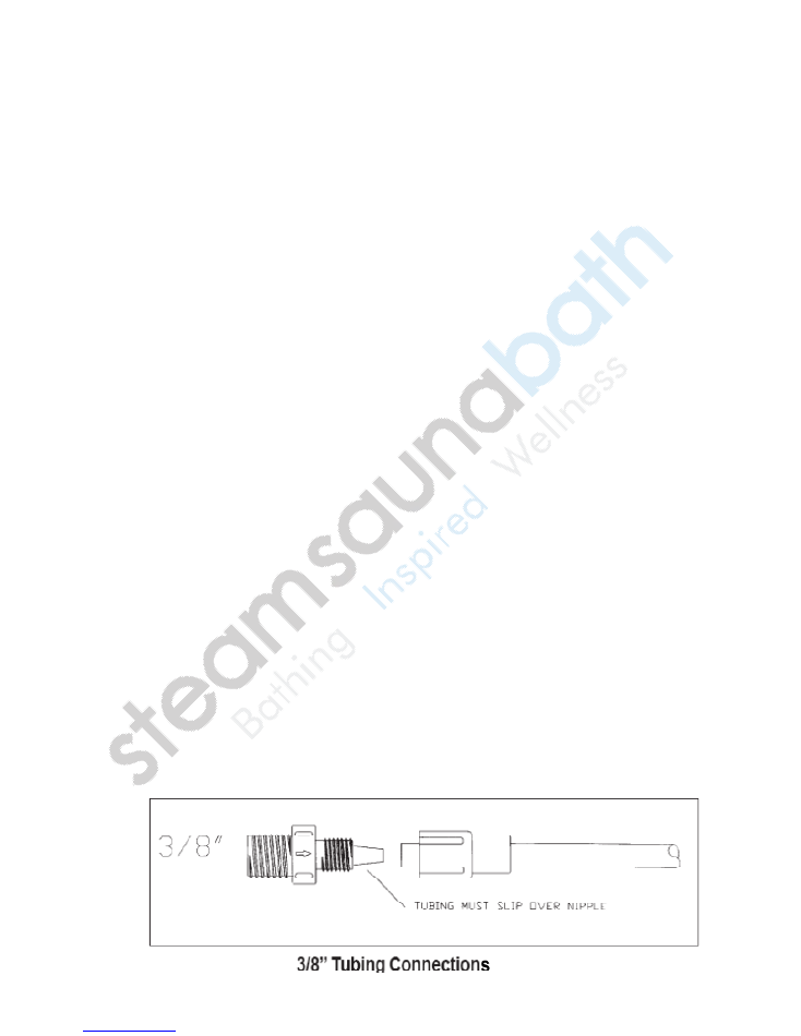
2. Tubing nuts
Do not over tighten tubing nut connectors. Tighten no more than ¼” turn after
the fitting contacts the seal. Hand tighten only.
Do not use a wrench or pliers
as they may damage the fittings. (See diagram below.) Do not use Teflon tape
except on 3-function valve NPT fitting.
Be sure to observe applicable local
plumbing codes.
WARNING: Clear flexible vinyl priming tubing is not intended for
pressurized or pump discharge use.
3. Tubing Connections
Page
6
E. Control (Aroma Switch)
1. Location
Determine the desired installation location for the aroma switch control. The
aroma switch has a 60’ integral low voltage cable and is designed to be installed
inside or outside the steam room as a matter of personal preference.
If aroma switch is installed inside the steam room, it must be located 4-5 feet
above the floor, on a vertical wall, convenient for user on/off operation and away
from steam head or steam emissions.
NOTE: For convenient use during steambathing, an aroma switch mounted
inside the steam room is most preferred.
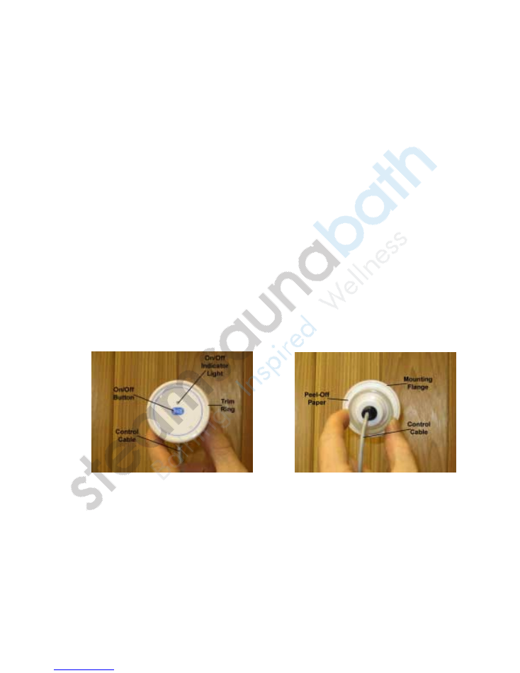
2. Mounting Aroma Switch
Make a 1
⅝
” diameter hole in desired control location. Route the aroma switch
integral control cable from the wall cut out to the
AromaMist
AromaMist
AromaMist
AromaMist
pump power
supply module. With a clean and dry mounting surface, remove the peel-off
paper from the back of the aroma switch, run a thin bead of 100% clear silicon
completely around the aroma switch mounting flange and press the control
against the wall until the adhesive sticks. Connect the aroma switch cable to the
3-pin terminal on the power supply module to complete the aroma switch
installation.
Aroma Switch (Front View)
Aroma Switch (Back View)
Page
7
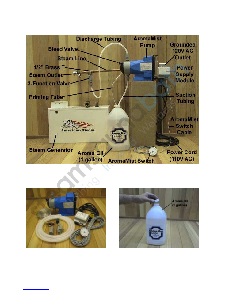
F. Typical Installation
G. Step By Step
AromaMist
AromaMist
AromaMist
AromaMist
Pump Installation
1. Verify carton components and mount
pump on a level surface. See details on
locating the pump on page 4 of this
manual.
2. Locate
AromaMist
AromaMist
AromaMist
AromaMist
brand aroma oil and
remove cap.
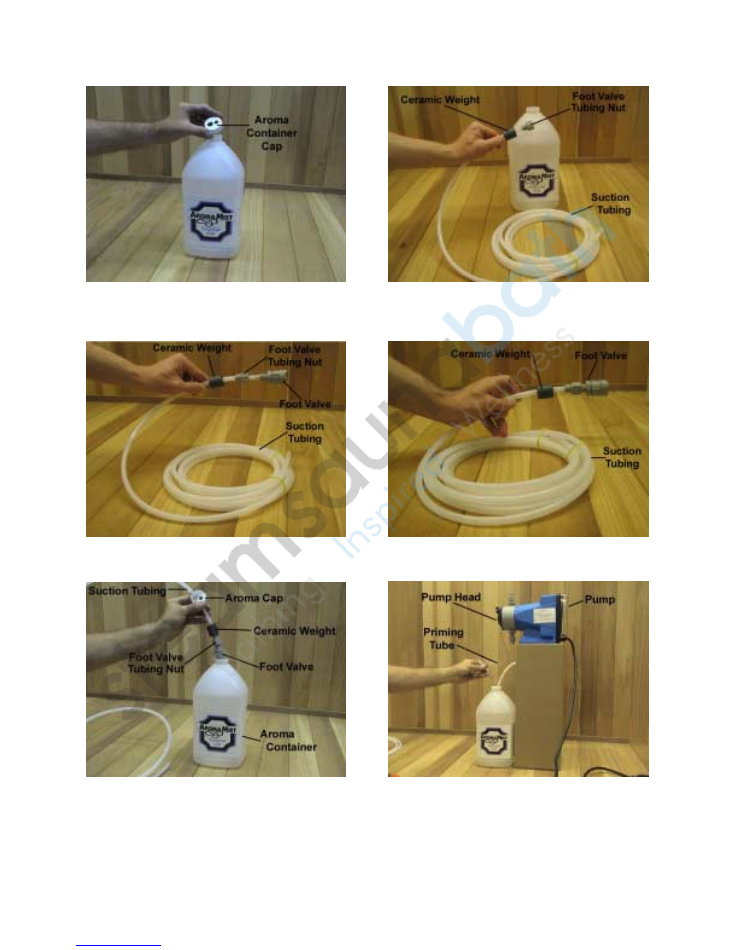
G. Step By Step
AromaMist
AromaMist
AromaMist
AromaMist
Pump Installation (continued)
Page 8
3. Drill 2 holes in aroma container cap:
one
⅜
" hole for clear vinyl priming tube
and one
7
/
16
" hole for the more rigid
suction tubing.
5. Install foot valve next, pushing firmly
until suction tubing is flush against foot
valve threads.
7. Thread suction tubing through aroma
container
7
/
16
" hole and insert
components into aroma oil container.
Foot valve should remain vertical and
resting on aroma container bottom.
4. Beginning with the more rigid 20'
suction tubing, cut the required length
necessary and string the ceramic weight
followed by the foot valve nut.
6. Secure foot valve nut. Hand tighten
only.
8. With aroma container located beneath
pump head and cap secure, insert clear
vinyl priming tube through
⅜
” hole in
cap to bottom of aroma container.
G. Step By Step
AromaMist
AromaMist
AromaMist
AromaMist
Pump Installation (continued)
Page 9
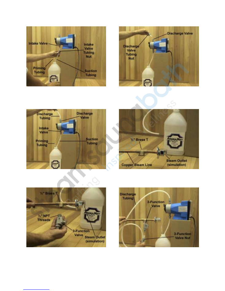
9. Remove intake valve tubing nut and
red protective cap, slip nut on the
suction tubing, secure suction tubing on
intake valve and hand tighten intake
valve nut.
11. All pump priming, discharge and
suction tubing connections should
appear as detailed above.
13. Locate 3-function valve, apply Teflon
tape or joint compound to ½” NPT
threads and secure 3-function valve in
bottom of ½” T.
10. Cut required length of discharge
tubing, remove discharge valve tubing
nut and red protective cap, slip nut on
discharge tubing, secure discharge
tubing and hand tighten nut.
12. Cut existing steam generator steam
line and solder in provided ½” brass T.
Steam outlet head shown for illustration
purposes only.
14. Remove 3-function valve tubing nut,
slip nut on discharge tubing and hand
tighten nut to 3-function valve.
G. Step By Step
AromaMist
AromaMist
AromaMist
AromaMist
Pump Installation (continued)
Page 10
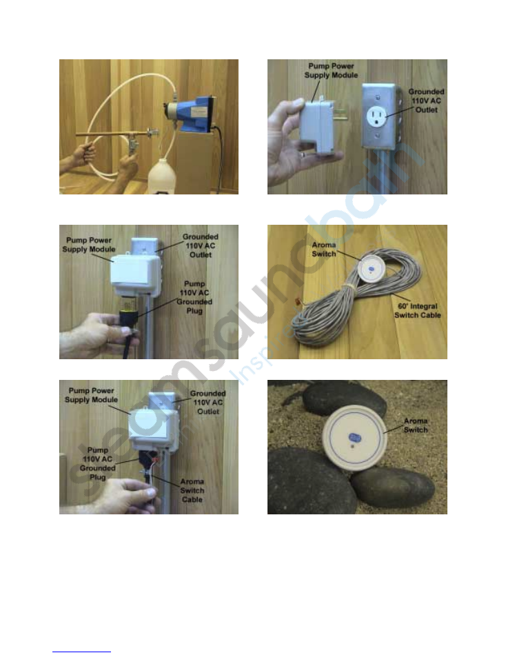
15. All pump connections should appear
as detailed above. Steam head shown
for illustration purposes only.
17. Plug in pump 110V AC power supply
cord to power supply module.
16. Run a 110V AC grounded outlet
within 6’ of pump installation location
and insert pump power supply module.
18. Locate pump switch with integral 3-
pin 60’ low voltage cable
19. Cut a 1
⅝
” hole in desired switch
installation location and run control
cable from switch mounting hole to
power supply module 3-pin connection
terminal pressing firmly to affix cable.
See page 6 for control installation
details.
20. After testing pump switch for
operation, secure in newly created 1
⅝
”
diameter hole using 100% clear silicon
and let dry for 24 hours prior to use.
Page 11
V.
Start-Up -
Primimg the
AromaMist
AromaMist
AromaMist
AromaMist
pump
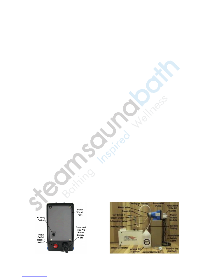
CAUTION: Please read all 7 steps prior to priming the
AromaMist
AromaMist
AromaMist
AromaMist
pump
1.
Insert
AromaMist
AromaMist
AromaMist
AromaMist
pump power supply cord into pump power supply module.
2.
Insert
AromaMist
AromaMist
AromaMist
AromaMist
pump power supply module into grounded 110V AC outlet.
3.
Power up integral
AromaMist
AromaMist
AromaMist
AromaMist
pump rocker switch located on the pump panel
face. Switch LED will light when on.
4.
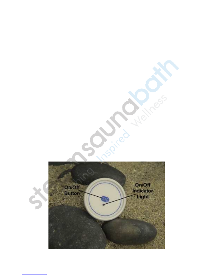
Initiate the remote-mounted aroma switch by pressing gently on jet icon.
Aroma LED will light when on and pump will start moving aroma oil.
5.
With
AromaMist
AromaMist
AromaMist
AromaMist
pump on, push and hold the priming button located on the
pump panel face. This will initiate the priming process where aroma oil will be
drawn at a faster rate to fill the suction and discharge tubing. Releasing prime
button will stop priming process.
6.
With pump in priming mode, if fluid begins moving up suction tubing without
hesitation, bleed valve adjustment is not required. If fluid is not moving up suction
line, open bleed valve (counter-clockwise) approximately one (1) turn or until fluid
begins to move. When fluid level reaches the pump head assembly, close bleed
valve allowing fluid to flow through pump head and up to the steam line.
NOTE:
Do not over tighten bleed valve as damage may occur.
7.
Once aroma oil has reached the 3-function valve, release the priming tubing
and turn off the remote-mounted aroma switch.
AromaMist
AromaMist
AromaMist
AromaMist
pump is now ready
for use.
NOTE: Pump integral On/Off rocker switch must stay in the on position to
operate pump from remote-mounted aroma switch.

Page 12
VI. Operation Warnings
1. Do not use a sharp object or fingernail to press on the
AromaMist
AromaMist
AromaMist
AromaMist
pump switch.
Sharp objects will penetrate the face plate and damage the aroma switch.
2. Do not pump unapproved aroma oils with the
AromaMist
AromaMist
AromaMist
AromaMist
pump system. Use of
foreign oils may pose serious health hazards or damage to equipment.
3. Check with a physician prior to using the
AromaMist
AromaMist
AromaMist
AromaMist
pump system if you are
pregnant, have a coronary condition, are in poor health, are using medications or
drugs, have allergies or are being treated for any other medical conditions.
4. Children under the age of 17 should not use a steambath.
5. Exit the steam shower immediately if you feel uncomfortable, faint, dizzy or tired.
6. Aroma oil residue, steam shower condensation and moisture will cause the
steam room floor and other surfaces to become slippery. Installation of non-skid
floor materials and caution while walking is always recommended.
7. Do not walk near or by steam outlet head during steam shower operation.
8. Do not activate the
AromaMist
AromaMist
AromaMist
AromaMist
pump while the steam generator is off or not
producing steam. If pump is accidentally activated with steam generator off,
operate steam generator for 10 minutes with aroma switch in the off position to
flush the steam line. Follow with water spray to wash the steam shower floor of
excess aroma oil residue.
9. Aroma oil is an oil-based product which will make the steam shower floor
slippery. It is important to wash down floor with water immediately after each use
and use caution while walking.
10. Should you have any questions about the safe installation or operation of the
AromaMist
AromaMist
AromaMist
AromaMist
pump system, we encourage you to call us at (847) 465-8990.
Page 13
VII. Operation
During the steambath session, initiate the
AromaMist
AromaMist
AromaMist
AromaMist
pump by pressing the mist icon
below the on/off LED indicator light on the aroma switch. Once activated, the red LED
will light and the aroma oil will begin to flow into the steam line.
Once satisfied with the steam shower aroma, depress the aroma switch once again to
stop the flow of aroma oil. The red on/off LED will indicate the pumps status at all
times. Start and stop the aroma oil flow as required to maintain the desired steam
bathing fragrance.
NOTE: Frequent starting and stopping of aroma oil will not adversely affect the
AromaMist
AromaMist
AromaMist
AromaMist
pump.
The
AromaMist
AromaMist
AromaMist
AromaMist
pump has no adjustment for aroma oil flow rate. For increased
fragrance intensity, initiate the aroma switch earlier in the steambathing session.
NOTE: The
AromaMist
AromaMist
AromaMist
AromaMist
pump system has a built-in timer and, if not manually
turned off, will automatically operate for a 10-minute session.
For care of your aroma switch, only use mild soap and water on a soft cloth. Do not use
any abrasive or chemical cleansers.
CAUTION: Aroma oil is an oil-based product which will make the steam shower
floor slippery. It is important to wash down floor with water immediately after
each use and use caution while walking.
Page 14
VIII. Troubleshooting
Problem Cause
Remedy
Pump
does not
achieve or
maintain
prime
Air Trapped in suction
line
Foot Valve
contaminated or
improperly installed
Excessive lift
Suction fittings not
properly tightened
Worn or contaminated
check valves
Kink or pinch in
suction tube
Low chemical level
Straighten suction line so as to eliminate high
spots
Inspect foot valve screen and assure that foot
valve is in a vertical position below fluid level
Maximum suction lift is 5 feet with water or fluids
of similar specific gravity; less with heavier
liquids such as acids. Mount pump in a lower
position relative to the chemical container.
Check fittings. Over tightening may cause
restriction. Conversely, if
any
leakage occurs,
pump will suck air and fail to prime.
Inspect check valves in fluid end for cleanliness.
Clean or replace as necessary.
Inspect suction tube through its full length to
assure that there are no kinks or other
restrictions
Check fluid level in chemical supply tank
Insufficient
fluid
Obstruction in suction
line
Clogged foot valve
screen
Diaphragm worn or
torn
Electronic failure
Check suction line for obstructions, clogging,
kinks or pinch points
Clean or replace foot valve screen
Replace diaphragm, making sure that it is
screwed on fully to shoulder of shaft
Consult factory
Excessive
fluid
Failure of anti-siphon
valve
Improper stroke length
Inspect or add anti-siphon valve. This is caused
when system is in a vacuum condition.
Consult factory
Pump will
not run
Pump not turned on or
not plugged in
Electronic failure
Check outlet with meter to assure that 95-135
VAC is present on 120V systems and that the
power supply cord is in good condition and
plugged in
Consult dealer or factory

Page 15