Full Text Searchable PDF User Manual
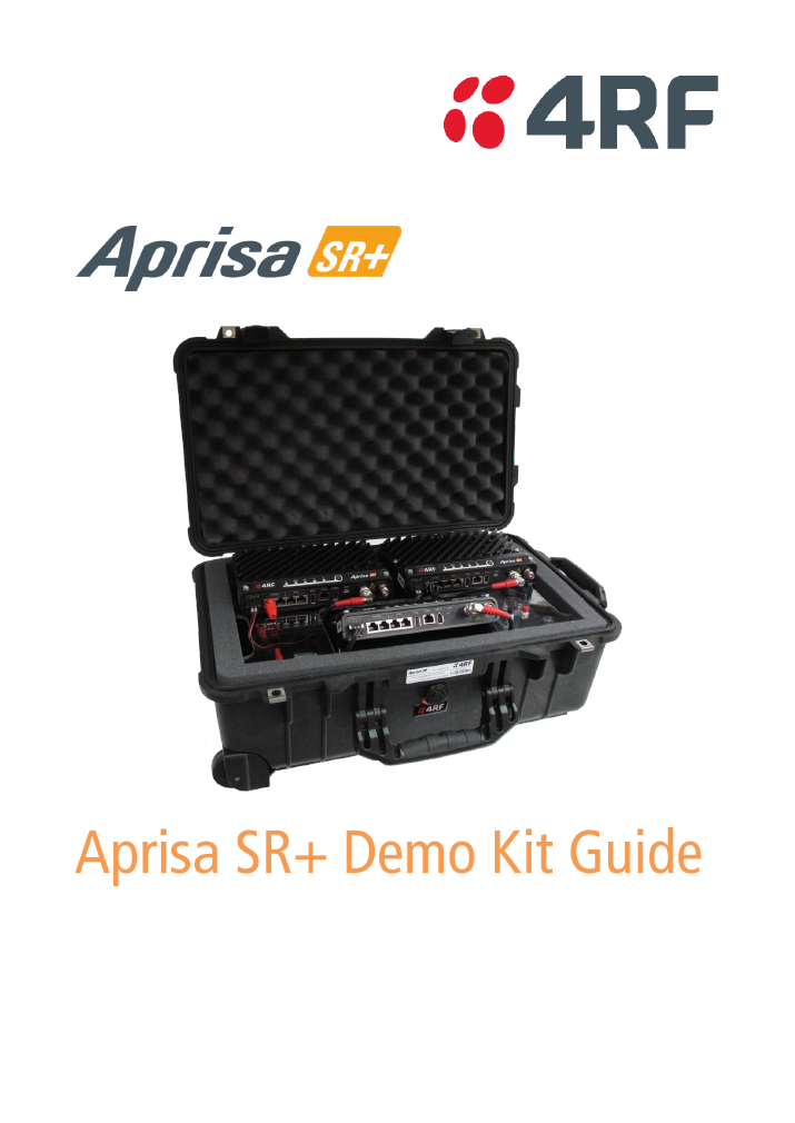
September 2018
Version 1.3.0

2 | Introduction
Aprisa SR+ Demo Kit Guide 1.3.0
Copyright
Copyright © 2018 4RF Limited. All rights reserved.
This document is protected by copyright belonging to 4RF Limited and may not be reproduced or
republished in whole or part in any form without the prior written permission of 4RF Limited.
Trademarks
Aprisa and the 4RF logo are trademarks of 4RF Limited.
Windows is a registered trademark of Microsoft Corporation in the United States and other countries. Java
and all Java-related trademarks are trademarks or registered trademarks of Sun Microsystems, Inc. in the
United States and other countries. All other marks are the property of their respective owners.
Disclaimer
Although every precaution has been taken preparing this information, 4RF Limited assumes no liability for
errors and omissions, or any damages resulting from use of this information. This document or the
equipment may change, without notice, in the interests of improving the product.

Introduction | 3
Aprisa SR+ Demo Kit Guide 1.3.0
Contents
Introduction ................................................................................ 4
Hardware ................................................................................... 5
Software .................................................................................... 5
Warning: .................................................................................... 5
Demonstration Setup ..................................................................... 6
Demonstration Settings .................................................................. 7
Demonstration Procedure .............................................................. 8
Advanced HMI 4RF SR+ SCADA Demo ......................................................... 10
Laptop Configuration and Installation ................................................. 10
SCADA Simulation / HMI ................................................................. 10
Default Configurations ................................................................. 11
Channel Access ........................................................................... 11
Security .................................................................................... 11
Serial Port Settings ....................................................................... 11
Ethernet Settings ......................................................................... 11
Layer 2 Filter.............................................................................. 12
4 | Introduction
Aprisa SR+ Demo Kit Guide 1.3.0
1.
Introduction
The following instructions outline the equipment and procedure for demonstrating the operation of the
Aprisa SR+. It runs through the steps to show the web browser management and Test Button operation.
The demo kit demonstrates;
•
concurrent Ethernet and RS-232 serial data communications between an Aprisa SR+ base station
and two Aprisa SR+ remote stations
•
utilizing the built in Moxa RTU to control various inputs and outputs
•
optional IP Camera operation
Demo Kit List
The Aprisa SR+ Demo Kit contains the following:
1.
3x Aprisa SR+ Radios (nominal 13.8 VDC)
2.
RF Interconnect cables, RF combiner / splitter and attenuators
3.
Universal power supply 90 to 264 VAC input, 24 VDC 6.25 A, 150W output
4.
Moxa RTU, RTU switch Inputs and RTU LED outputs
5.
Accessory kit of cables etc (located under the radios)
6.
Power Cable IEC to country specific power plug (located under the radios)
7.
Aprisa SR+ Demo Kit Guide
The Accessory Kit contains the following:
1x USB cable USB A to USB micro B, 1m
Cable to connect the radio management micro USB port to
a PC USB port for Command Line management
2x RJ45 to RJ45 patch cables 2m red
General purpose RJ45 to RJ45 patch cables for use with the
RJ45 to DB9 female adaptors for serial traffic connection to
the Aprisa SR+ serial ports
2x RJ45 to RJ45 patch cables 2m grey
General purpose RJ45 to RJ45 patch cables for Ethernet
port connections
2x RJ45 to DB9 female adaptors
RJ45 to DB9 female DCE adaptors for use with the 2m red
patch cables for serial traffic connection to the Aprisa SR+
serial ports
1x USB to Ethernet adaptor
USB to Ethernet adaptor for connecting Aprisa SR+ Ethernet
ports to a PC USB port for management with SuperVisor
2x RS-232 serial to USB converter cables 0.4m
RS-232 DB9 male DTE to USB converter for connecting
Aprisa SR+ serial ports to a PC USB port for RS-232 serial
traffic testing
1x USB to RS-232 serial converter cable 1.8m
USB converter to RS-232 DB9 female DCE for connecting the
Aprisa SR+ USB port to an RS-232 device for serial traffic
testing
1x serial port loopback plug
RJ45 RS-232 serial loopback plug with red boot fitted
1x USB flash drive
USB flash drive containing:
•
Drivers and applications
•
Aprisa SR+ product collateral
•
Aprisa SR+ product software

Introduction | 5
Aprisa SR+ Demo Kit Guide 1.3.0
Equipment List
The following equipment is required to perform the tests and demonstrations as described in this
document.
Hardware
1.
Aprisa SR+ Demo Kit
2.
Laptop or PC
3.
IP Camera (optional extra
to purchase please contact your 4RF representative)
Software
The software required for the demonstration has been provided on the included USB Flash Drive.
1.
Web Browser (Internet Explorer)
2.
Advanced HMI 4RF SR+ SCADA Demo
3.
Terminal Emulator (HyperTerminal or Putty)
Warning:
On low capacity radio based IP networks used for SCADA, general network broadcast traffic can overload
the radio communication channel. This broadcast traffic may come from servers, laptops, and other
network devices e.g. DHCP requests, DNS traffic, NetBIOS traffic, and ARP requests.
Low capacity radio networks must be isolated from other LANs such as main SCADA and corporate LANs
using routers to block traffic not intended for the SCADA radio network.
This needs to be considered when demonstrating and testing the Aprisa SR+ radios.
6 | Demonstration Setup
Aprisa SR+ Demo Kit Guide 1.3.0
2.
Demonstration Setup
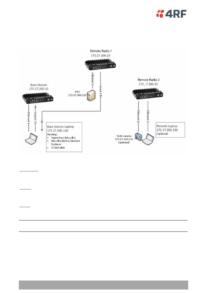
The following is a typical demonstration setup:
When setting up the equipment for testing, note the following:
Attenuators
In a bench setup, there should be 60 - 80 dB at up to 1 GHz of 50 ohm coaxial attenuation, capable of
handling the transmit power of +37 dBm (5 W) between the radios
’
antenna connectors.
Splitter
The splitter should be 50 ohm coaxial up to 1 GHz and capable of handling the transmit power of +37 dBm
(5 W).
Cables
Use double-screened coaxial cable that is suitable for use up to 1 GHz at
≈
1 metre.
CAUTION:
Do not apply signals greater than +10 dBm to the antenna connection as they can damage the
receiver.
Demonstration Settings | 7
Aprisa SR+ Demo Kit Guide 1.3.0
3.
Demonstration Settings
PC Settings
The following are the PC settings required for this demo:
Network Connections
Terminal Emulator
Local Area Connection
COM Port Settings
Properties
BaudRate
38400
Internet Protocol TCP/IP Settings
Data
8 bit
IP Address
172.17.200.110
Parity
None
Subnet Mask
255.255.0.0
Stop
1 bit
Default Gateway
0.0.0.0
(none)
Flow Control
None
Advanced TCP/IP Settings
Terminal Settings
WNS
Disable NetBIOS over TCP/IP
ASCII Receiving
CR+LF
(line feed after receiving a text file)
Wireless Network Connection
Disable
Character delay
0
Line delay
0
Radio Settings
The demo kit radios have been preset with User Defaults. The radio settings can be reset to these
defaults if required.
On SuperVisor, click on Maintenance > Defaults > Restore User Defaults
When activated, all radio parameters will be set to User Defaults.

8 | Demonstration Procedure
Aprisa SR+ Demo Kit Guide 1.3.0
4.
Demonstration Procedure
All commands to be typed are shown in
italics
.
Basic Operation
1.
Open Internet Explorer and access 172.17.200.10
a.
Username:
admin
b.
Password:
admin
2.
Show basic Web browser management
a.
Tab through the various screens and explain about remote management
3.
Show Test Button operation
a.
Press and hold the Test Button on remote radio 1 until the LEDs flash. Five green LEDs
should appear indicating >-80 dBm RSSI
b.
Disconnect the RF cable on remote radio 1 and hold it close to the RF connector. The
LEDs should turn orange
c.
Pull the cable away completely and the LEDs should turn red
d.
Reconnect the cable. The LEDs should turn back to all green
e.
Press and hold the Test Button until the LEDs flash to exit the test mode
4.
Open Terminal Emulator configured for RS-232 serial data and show transfer of a text file
a.
Fit the RJ45 RS-232 loopback plug to remote radio 1 serial port 1
b.
Send a text file from the base station. The details should reappear on the screen
indicating that the file has been sent to that remote station, looped back at the remote
station RS-232 serial port and sent back to the base station
c.
Remove the RS-232 loopback connector from the remote radio 1 and re-demonstrate
showing the break in the loopback connection
5.
Open cmd window and show Ethernet data transfer
note the flashing of Tx and Rx LEDs
a.
ping 172.17.200.20
b.
ping 172.17.200.30
6.
Show data compression
a.
In cmd window:
ping 172.17.200.30 l 1000
b.
Ping test should show transfer of 1000 bytes to be almost as fast as the 32 byte transfer
from previous test
7.
Show Ethernet and RS-232 serial. This test pings Remote Station 2 and loops back serial data
through remote radio 1
a.
Fit the RJ45 RS-232 loopback plug to remote radio 2 serial port 1
b.
In cmd window:
ping 172.17.200.20 t
c.
With the Terminal Emulator, send serial data
d.
In cmd window Ctrl C to stop the Ethernet test

Demonstration Procedure | 9
Aprisa SR+ Demo Kit Guide 1.3.0
8.
Show RSSI change
a.
In Web browser, browse to the base station Maintenance Summary page and note the RSSI
b.
Browse to the remote radio 1 Radio Setup page
c.
Change the Tx Power from +37 dBm to +27 dBm and save this change
d.
Return to the base station Maintenance Summary page
e.
In cmd window:
ping 172.17.200.20
f.
In Web Browser RSSI should drop by 10 dB
g.
Return to the remote radio 1 Radio Setup page and change the power back to +37 dBm
10 | Demonstration Procedure
Aprisa SR+ Demo Kit Guide 1.3.0
Advanced HMI 4RF SR+ SCADA Demo
Laptop Configuration and Installation
A USB flash drive containing all of the required software has been included with this demo kit. All of the
software is required to be loaded on the base station laptop.
1.
From the 4RF demo kit USB flash drive, open the 4RF Advance HMI Install folder
2.
Launch the setup.exe and install with default configurations
3.
The program will now appear in the computers start menu
SCADA Simulation / HMI
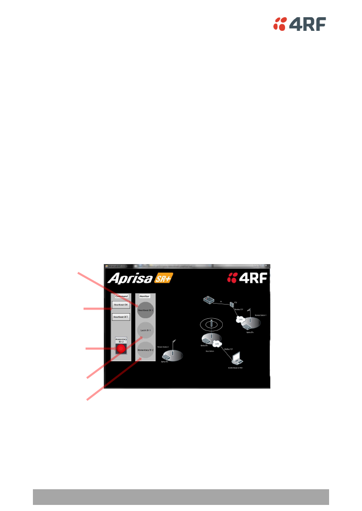
Ensure the base station laptop is configured to the correct IP address: 172.17.200.110
1.
Ensure the base station laptop is connected to Ethernet Port 1 of the base station radio
2.
Ensure the Moxa RTU is powered on and displays the following LEDs:
a.
Power: orange
b.
Ready: green
c.
Port 1: green
3.
On the base station laptop, go to Start menu > All Programs > 4RF Advanced HMI
4.
Proceed with selecting the various inputs via either the laptop or the switches on the demo kit and
observe the results
5.
Close the application by closing the window
Momentary Button
Turns on an off the orange
switchbox LED
Heartbeat Buttons
Turns on and off the 2sec
heartbeat LED
(blue/green)
Momentary LED
Continually polls the
heartbeat LED and
displays indicates the
state
Black switch indicator
Indicates the state of the
black latching switch
Red switch indicator
Indicates the state of the
red momentary switch

Default Configurations | 11
Aprisa SR+ Demo Kit Guide 1.3.0
5.
Default Configurations
The Aprisa SR+ Demo Kit has been preconfigured to specific parameters in keeping with the
demonstrations outlined in this document.
Should at any stage parameters be changed and a reset to the original state is required, the following
procedures may be used.
Aprisa SR+ Radios
The demo kit radios have been preset with User Defaults. The radio settings can be reset to these
defaults if required.
1.
On SuperVisor, click on Maintenance > Defaults > Restore User Defaults. When activated, all radio
parameters will be set to User Defaults.
The configurations set have been detailed below:
Channel Access
Access mode:
access request
Default/Serial/Ethernet
Packet Time-to-live (ms):
0
Default/Serial/Ethernet
Packet back off (ms):
4 or 2
Security
ICMP:
enabled
Serial Port Settings
Baud rate:
115200
Data Bits:
8
Parity:
n
Stop Bits:
1
Flow Control:
RTS/CTS
Ethernet Settings
Ethernet Port 1:
User+ Management
Ethernet Port 2:
User+ Management
Ethernet Bridge OTA:
Enabled
12 | Default Configurations
Aprisa SR+ Demo Kit Guide 1.3.0
Layer 2 Filter
Layer 2 Filter
enabled
Layer 2 Filter Rules
Source
MAC Address
Destination
MAC Address
Protocol Type
Allow ARPS
FF:FF:FF:FF:FF:FF
FF:FF:FF:FF:FF:FF
ARP
Allow Unicasts from ANY source FF:FF:FF:FF:FF:FF
FE:FF:FF:FF:FF:FF
ANY
Moxa RTU
The RTU has been preconfigured to the requirements of this demo kit. However, should the settings be
changed in any way, the parameters can be re-configured by following these steps:
The factory default IP address of the RTU (MOXA ilogik E2124) is 192.168.127.254
1.
Open Web browser and enter: 192.168.127.254
2.
Navigate to Network Settings > Ethernet Configuration
a.
Set the IP address to: 172.17.200.220
b.
Set the subnet mask to: 255.255.0.0
c.
Set the gateway to: 0.0.0.0
3.
Navigate to I/O Settings > D0 Channel Settings
a.
Configure D0 channel 3
to Power Settings “ON”
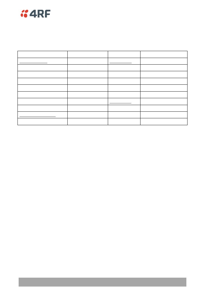
Laptop
Network Connections
Terminal Emulator
Local Area Connection
COM Port Settings
Properties
BaudRate
38400
Internet Protocol TCP/IP Settings
Data
8 bit
IP Address
172.17.200.110
Parity
None
Subnet Mask
255.255.0.0
Stop
1 bit
Default Gateway
0.0.0.0
(none)
Flow Control
None
Advanced TCP/IP Settings
Terminal Settings
WNS
Disable NetBIOS over TCP/IP
ASCII Receiving
CR+LF
(line feed after receiving a text file)
Wireless Network Connection
Disable
Character delay
0
Line delay
0